bdi
RDI
JTAG interface for RDI Debuggers, BDI1000 User Manual 8
© Copyright 1999-2003 by ABATRON AG V 1.10
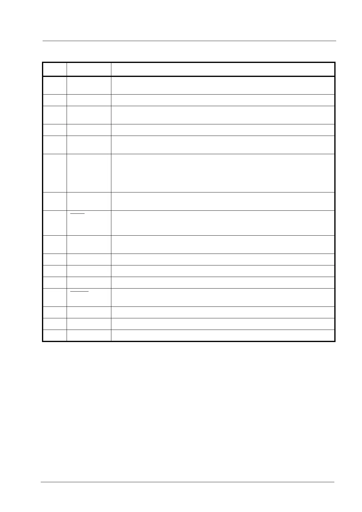
BDI TARGET B Connector Signals:
Pin Name Describtion
1 TDO
JTAG Test Data Out
This input to the BDI1000 connects to the target TDO line.
2 reserved
3 TDI
JTAG Test Data In
This output of the BDI1000 connects to the target TDI line.
4 reserved
5RTCK
Returned JTAG Test Clock
This input to the BDI1000 connects to the target RTCK line.
6 Vcc Target
1.8 – 5.0V:
This is the target reference voltage. It indicates that the target has power and it is also used
to create the logic-level reference for the input comparators. It also controls the output logic
levels to the target. It is normally connected to Vdd I/O on the target board.
7 TCK
JTAG Test Clock
This output of the BDI1000 connects to the target TCK line.
8 TRST
JTAG Test Reset
This open-drain / push-pull output of the BDI1000 resets the JTAG TAP controller on the
target. Default driver type is open-drain.
9 TMS
JTAG Test Mode Select
This output of the BDI1000 connects to the target TMS line.
10 reserved
11 reserved
12 GROUND
System Ground
13 RESET
System Reset
This open collector output of the BDI1000 is used to reset the target system.
14 reseved
15 reseved
16 GROUND
System Ground