bdi
RDI
JTAG interface for RDI Debuggers, BDI1000 User Manual 3
© Copyright 1999-2003 by ABATRON AG V 1.10
1 Introduction
The BDI1000 adds JTAG based debugging to RDI compatible debuggers (e.g. ADW from ARM Ldt).
With the BDI1000, you control and monitor the microcontroller solely through the stable on-chip de-
bugging services. You won’t waste time and target resources with a software ROM monitor, and you
eliminate the cabling problems typical of ICE’s. This combination runs even when the target system
crashes and allows developers to continue investigating the cause of the crash. A RS232 interface
with a maximum of 115 kBaud and a 10Base-T Ethernet interface is available for the host interface.
The configuration software is used to update the firmware and to configure the BDI1000 so it works
with the RDI compatible debugger.
1.1 BDI1000
The BDI1000 is a processor system in a small box. It implements the interface between the JTAG
pins of the target CPU and a 10Base-T Ethernet / RS232 connector. BDI1000 is powered by a
MC68331, 256Kbyte RAM and a flash memory of 512Kbyte. As a result of consistent implementation
of lasted technology, the BDI1000 is optimally prepared for further enhancements. The firmware and
the programmable logic of the BDI1000 can be updated by the user with a simple Windows based
configuration program. The BDI1000 supports target system voltages from 1.8 up to 5 Volts.
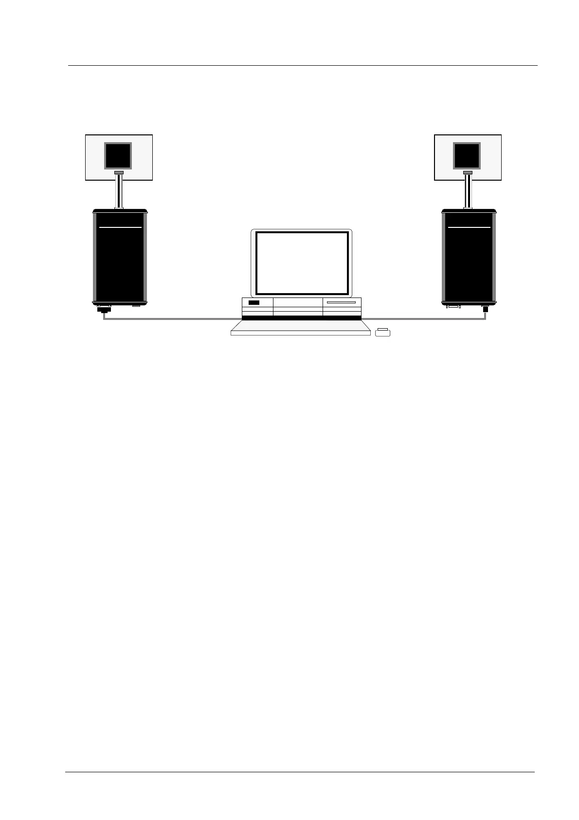
PC Host
RDI
Debugger
BDI1000
AA
AA
bb
bb
aa
aa
tt
tt
rr
rr
oo
oo
nn
nn
AA
AA
GG
GG
SS
SS
ww
ww
ii
ii
ss
ss
ss
ss
MM
MM
aa
aa
dd
dd
ee
ee
Target System
JTAG Interface
Ethernet (10 BASE-T)
BDI1000
AA
AA
bb
bb
aa
aa
tt
tt
rr
rr
oo
oo
nn
nn
AA
AA
GG
GG
SS
SS
ww
ww
ii
ii
ss
ss
ss
ss
MM
MM
aa
aa
dd
dd
ee
ee
Target System
JTAG Interface
RS232
ARM
ARM