16 IM/261Gx/Ax-EN Rev. 08 | 261Gx, 261Ax
Change from two to one colu mn
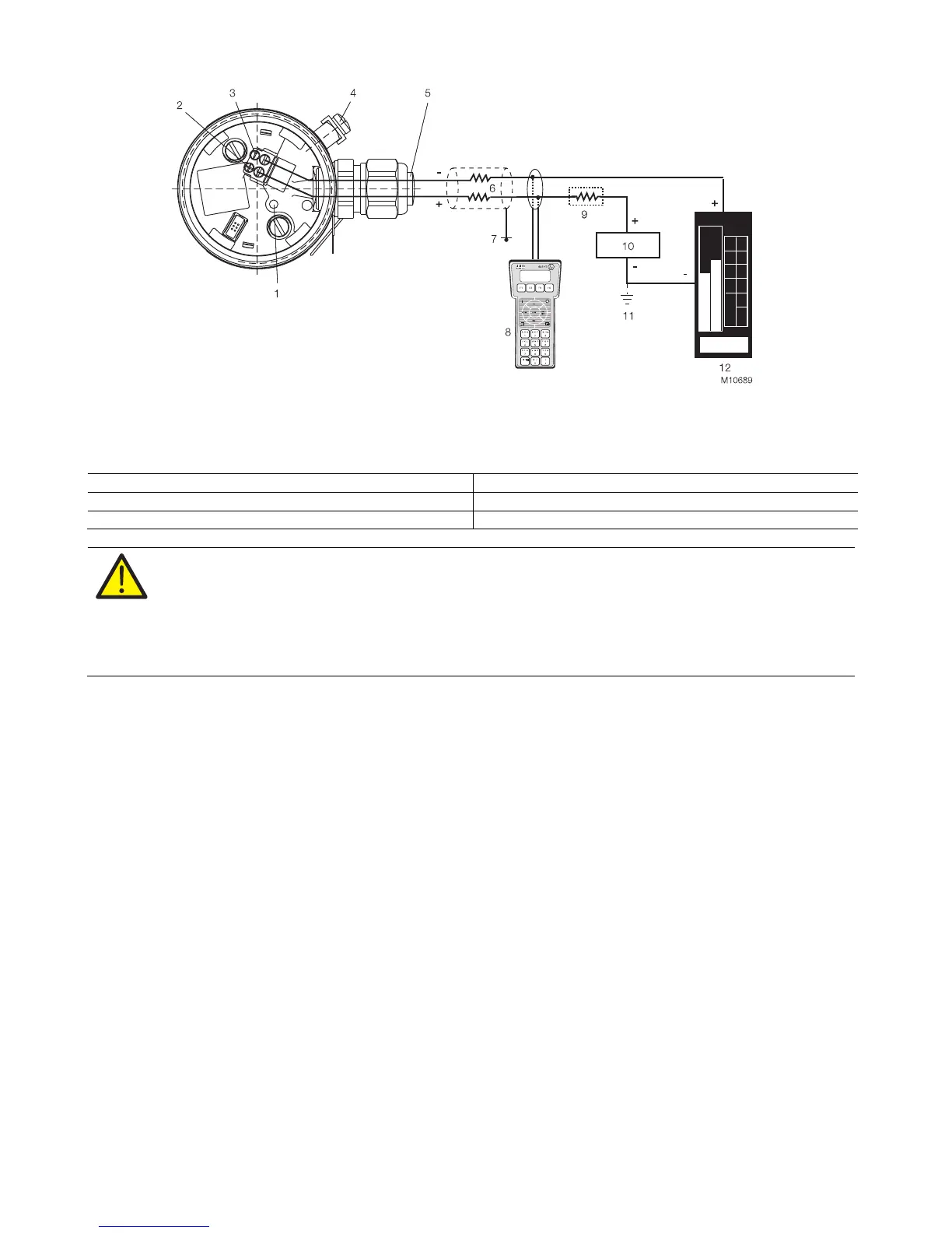
5.2 Electrical connection in the cable connection area
Fig. 7
1 Pushbutton for lower/upper range values | 2 + Signal screw terminals for leads with cross-section of 0.5 … 1.5 mm
2
|
3 - Signal screw terminals for leads with a cross-section of 0.5 … 1.5 mm
2
| 4 Grounding / equipotential bonding terminal (optional) |
5 Cable entry | 6 Line load | 7 Grounding | 8 Handheld terminal | 9 Resistor (min. 250 Ω) |
10 Power supply / power supply unit | 11 Optional ground | 12 Receiver
application Permissible voltage range of power supply
Transmitter operated outside the potentially explosive atmosphere. 11 … 42 V
Transmitter operated inside the potentially explosive atmosphere. 11 … max. 30 V (intrinsically safe)
WARNING! Risk of explosion!
If, when using transmitters with type of protection "intrinsic safety", an ammeter is connected to the output circuit
or a modem is connected in parallel while there is a risk of explosion, the sums of the capacitances and
inductances of all circuits, including the transmitter (see EC-type-examination certificate) must be equal to or less
than the permissible capacitances and inductances of the intrinsically safe signal circuit (see EC-type-examination
certificate for the power supply unit).
Only passive or explosion-proof devices or indicators may be connected.