10 OI/266/LowP-EN Rev.A | 2600T Series Pressure transmitters
5 Mounting
5 Mounting
5.1 General
Study these installation instructions carefully before proceeding.
Failure to observe the warnings and instructions may cause a
malfunction or personal hazard. Before installing the
transmitter, check whether the device design meets the
requirements of the measuring point from a measurement
technology and safety point of view.
This applies in respect of the:
— Explosion protection certification
— Measuring range
— Gauge pressure stability
— Temperature
— Operating voltage
The suitability of the materials must be checked as regards
their resistance to the media. This applies in respect of the:
— Gasket
— Process connection, isolating diaphragm, etc.
In addition, the relevant directives, regulations, standards, and
accident prevention regulations must be observed (e.g., VDE/
VDI 3512, DIN 19210, VBG, Elex V, etc.). Measurement
accuracy is largely dependent on correct installation of the
pressure transmitter and, if applicable, the associated
measuring pipe(s). As far as possible, the measuring setup
should be free from critical ambient conditions such as large
variations in temperature, vibrations, or shocks.
Important. If unfavorable ambient conditions cannot be avoided for
reasons relating to building structure, measurement technology, or
other issues, the measurement quality may be affected. If a remote
seal with capillary tube is installed on the transmitter, the additional
operating instructions for remote seals and the related data sheets
must be observed.
5.2 IP protection & designation
The housings for 266 transmitters are certified as conforming to
protection type IP66 / IP67 (according to IEC 60529) or NEMA
Type 4X (according to NEMA 250).
The first number indicates the type of protection the integrated
electronics have against the entry of foreign bodies, including
dust.
“6” means that the housing is dust-proof (i.e., no ingress of
dust). The second number indicates the type of protection
the integrated electronics have against the entry of water.
The second number indicates the type of protection the
integrated electronics have against the entry of foreign
bodies, including water.
“6” means that the housing is protected against water;
specifically, powerful jets of water under standardized
conditions.
“7” means that the housing is protected against water;
specifically, against the effects of temporary immersion in
water under standardized water pressure and temporal
conditions.
5.3 Mounting the transmitter
5.3.1 Transmitter factory configuration consideration
The 266 pressure transmitter in your hands has been factory
calibrated to reflect the published declared performance
specification; no further calibration is required in normal
condition. ABB typically configures 266 pressure transmitters
according to the user requirements. A typical configuration
includes:
— TAG number
— Calibrated span
— Output linearization
— LCD display configuration
5.3.2 Hazardous area considerations
The transmitter must be installed in hazardous area only if it is
properly certified. The certification plate is permanently fixed on
the neck of the transmitter top housing. The 266 Pressure
Transmitter Line can have the following certifications:
FM Approvals US and FM Approvals Canada (option code EB):
— Explosionproof (US): Class I, Div. 1, Groups A, B, C, D
Class I, Zone 1 AEx d IIC T4
— Explosionproof (Canada): Class I, Div. 1, Groups B, C, D
Class I, Zone 1 Ex d IIC T4
— Dust Ignitionproof: Class II, Div. 1, Groups E, F, G
Warning – General Risk for model 266 used in zone 0. Model
266 enclosure contains aluminum and is considered to present a
potential risk of ignition by impact or friction. Care must be taken into
account during installation and use to prevent impact or friction.
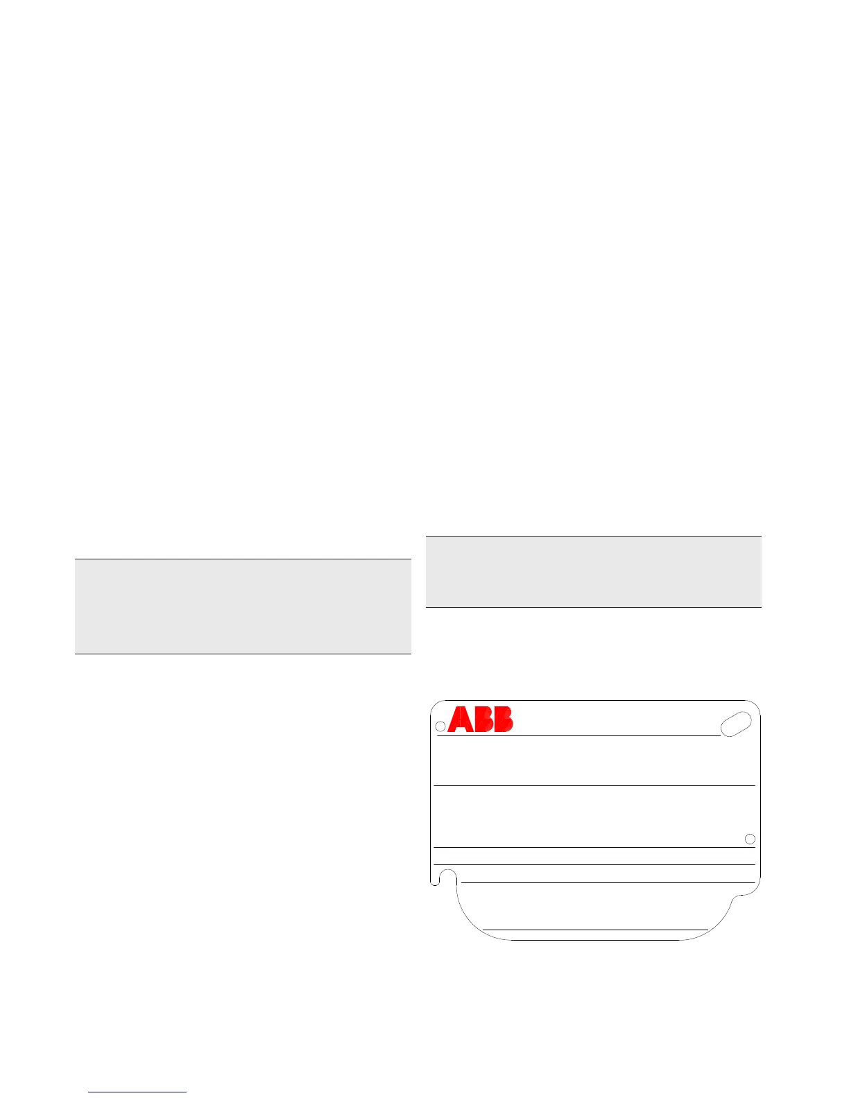
Figure 4: 266 nameplate with PED data
Local keys below label
PRODUCT CODE
SEAL-H
SEAL-L
SPEC.REQUEST
LRL/URL
SPAN LIMITS
POWER SUPPLY
OUTPUT SIGNAL
ABB S.p.A.
Made in Italy
TS
PS
SERIAL\NUMBER
SENSOR DIAPH.-FILL
FLANGE/CONN.-GASKET/S
H DIAPH.-FILL
L DIAPH.-FILL
SEAL
HW Rev.
MD:
PED:
MWP/OVP
5.4.2 Devices with PS ≤200 bar
Devices with a permissible pressure PS ≤200 bar correspond
to article 3 paragraph (3). They have not been subject to a
conformity validation. These instruments were designed and
manufactured acc. to SEP Sound Engineering Practices.
5.4 Pressure Equipment Directive (PED) (97/23/CE)
5.4.1 Devices with PS >200
Devices with a permissible pressure PS >200 bar have been
subject to a conformity validation. The data label includes the
following specifications:

 Loading...


