2600T Series Pressure transmitters | OI/266/LowP-EN Rev.A 19
8 Operation
Important. This configuration procedure only changes the 1 … 5V
signal; it does not affect the physical process pressure (PV value)
also shown on the digital display or user interface. After performing
a correction, you must check the device configuration.
Important. Setting the lower range value by using this button is
possible if the write protection is not enabled.
8.5 Activation procedure and considerations for the
integrated LCD
The integral LCD HMI is integrated to the 266 communication
board. It can be used to visualize the process measured
variables as well as to configure the display and the transmitter.
In addition, diagnostic information is provided. To access the
functionality of the HMI the following activation procedure
needs to be carried out:
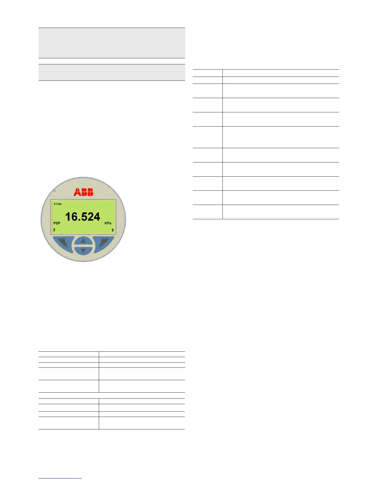
— Keys “Z” and “S” need to be pressed simuoltaneously for
5 seconds to initiate the configurable mode.
— Press key “S” to access the menu. Key “Z” give direct
access to the diagnostics visualization.
Figure 13: Display keypad
— The menu / submenu name is displayed above in the LCD
display.
— The number / line of the currently selected menu item is
displayed in the upper right of the LCD display.
— A scroll bar is located on the right edge of the LCD
display which shows the relative position of the currently
selected menu item within the menu.
— Both of the keys can have various functions.
The meaning of these buttons is displayed below in the
LCD display above the respective button.
Button (1) functionalities Meaning
Exit Exit menu
Back Back one submenu
Cancel
Exit without saving the selected parameter
value
Next
Select next position for entering numerical
values or letters
Button (4) functionalities
Meaning
Select Select submenu/parameter
Edit Edit parameter
Ok
Save selected parameter and display
stored parameter value
8.6 HMI as feedback of the local push button
operations
As consequence of the operations described in the section 8.2,
when the Z or S buttons are released, the feedback of the
executed operation is displayed in the bottom of the LCD
(same position as per diagnostic messages):
Message Description
! Oper Done
The push button operation has been successfully executed
! Proc Too
Low
The Pressure measured in input is too low and not
acceptable for the requested operation
! Proc Too
High
The Pressure measured in input is too high and not
acceptable for the requested operation
! New URV
Error
The Zero (Z) operation cannot be accepted because the
URV would be shifted outside the Upper Sensor limit
! Span Error
The Span (S) operation cannot be accepted because the
new URV would be too close to the LRV and their
difference lower than the Minimum Span value
! Oper
Disabled
The push button operation has been refused because the
Write Protection is enabled.
! LRV Too
Low
New LRV is too low and not acceptable for the requested
operation
LRV Too
High
New LRV is too high low and not acceptable for the
requested operation
URV Too
Low
New URV is too low and not acceptable for the requested
operation
URV Too
High
New URV is too high and not acceptable for the requested
operation
8.7 HMI menu structure
Follow the instruction on the screen to perform the
configuration of the different parameters.
Integrated LCD display allows the verification and the
parameterization of the basic configuration of the 266 pressure
transmitter. The menu driven structure will guide you to the
choice of the interface language, the engineering units, the LRV
and URV (Lower range value and Upper range value), the
transfer function, the damping time and the display line 1
visualization mode (the value that need to be visualized on the
LCD).

 Loading...


