18 OI/266/LowP-EN Rev.A | 2600T Series Pressure transmitters
8 Operation
8 Operation
8.1 Factory settings
Transmitters are calibrated at the factory to the customer’s
specified measuring range. The calibrated range is provided on
the name plate whereas the tag number on the additional tag
plate. The calibrated range and tag number are provided on the
name plate. If this data has not been specified, the transmitter
will be delivered with the following configuration:
Parameter Factory setting
Lower Range Value (LRV) (1V) Zero
Upper Range Value (URV) (5V) Upper Range Limit (URL)
Output transfer function Linear
Damping 1 second
Transmitter failure (alarm) Upscale (5.4V)
Optional LCD HMI scale 1 line PV
Important. Every configurable parameters listed here above can
easily be modified with an HART handheld terminal running proper
EDD file. Information regarding materials, filling liquid type, etc. is
stored inside the non-volatile memory of the device.
8.2 Configuration types
Pressure transmitters can be configured as follows:
— Configuration of the parameters for the lower and upper
range values via LCD keys.
— Configuration with a handheld terminal
8.3 Configuring the transmitter with LCD keys
The “lower range value” and “span” parameters can be set
directly on the transmitter using the LCD keys.
The transmitter has been calibrated by the manufacturer based
on the order information. The tag plate contains information on
the “lower range value” and “upper range value” set. In general,
the following applies:
The first pressure value (e.g., 0 mbar) is always assigned to the
1V signal (or 0%), while the second pressure value (e.g., 400
mbar) is always assigned to the 5V signal (or 100%). To change
the transmitter ranging apply the pressure for the “lower range
value” and “upper range value” to the measuring equipment.
Make sure that the measuring limits are not exceeded.
Important. Reducing station with adjustable pressure and
reference displays can be used as pressure generators.
When making the connection, please ensure that there are no
residual fluids (for gaseous testing materials) or air bubbles (for fluid
testing materials) in the impulse lines, since these can lead to errors
during inspection. Any potential measuring error for the pressure
generator should be at least three times smaller than the desired
measuring error for the transmitter. It is recommended that the
damping is set to 1 second.
8.4 LRV and URV configuration (1 ... 5 V ranging)
— Apply the lower range value for pressure (1 V) from the
process or from a pressure generator. The pressure must
be stable and applied with a high level of accuracy
<< 0.05 % (observing the set damping value).
— Remove instrument windowed cover.
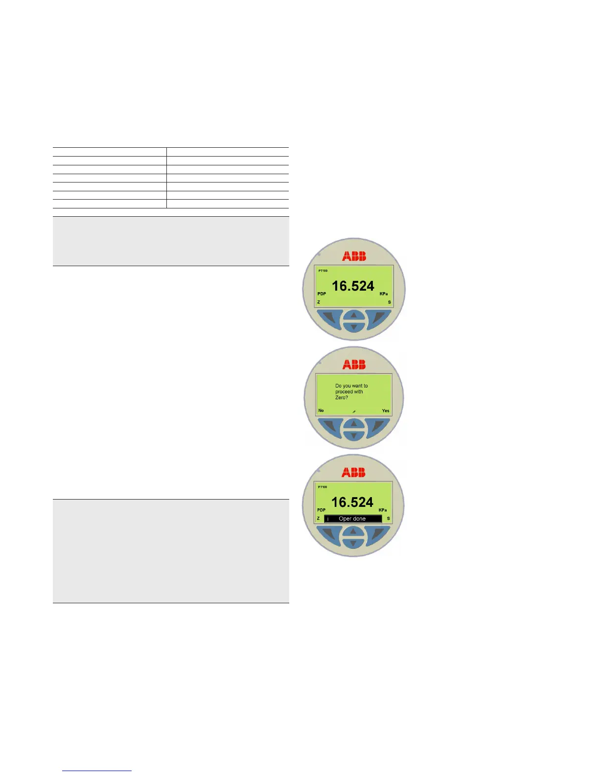
— Press “Z” LCD key for two seconds to set the output
signal to 1 V. Operator will be asked about proceeding
with the operation in progress. By depressing “Yes” a
small screwdriver icon will appear on the bottom of the
LCD. A confirmation string (“Oper Done”) will be shown on
device main screen on button release (for additional string
messages, refer to section ”8.6 HMI as feedback of the
local push button operations”). The span will remain
unchanged.
— Apply the pressure for the “upper range value” and wait
approx. 30 s until it has stabilized.
— Press “S” LCD key to set the output current to 5V and
adjust the Span. As described above, operator will be
asked about proceeding with the operation in progress. A
confirmation message will be shown at the end of Span
adjustment.
— Record the new settings. The respective parameter will be
stored in the non-volatile memory 20 seconds after the
confirmation has been given.
Figure 12: Operating with the display keypad

 Loading...


