Table 2.7: ETH 1 Pin Assignment
(Continued)
DescriptionSignalPin
Drain wireNot used7
Drain wireNot used8
2.4.5 Redundancy Link Interface
When using two LD 810HSE Ex Linking Devices as a redundant set, the redundancy
link interfaces (RDL) of both Linking Devices (primary and secondary) must be connected
by a cable, thus forming a “redundancy link”. If the redundancy link is not installed during
start-up (power-on), the LD 810HSE Ex will operate in non-redundant mode.
The interface is not galvanically isolated. Thus, make sure that there is no potential
difference between the two connected devices.
The maximum cable length is 0,5 m according to EMC requirements. The pin assignment
is as follows:
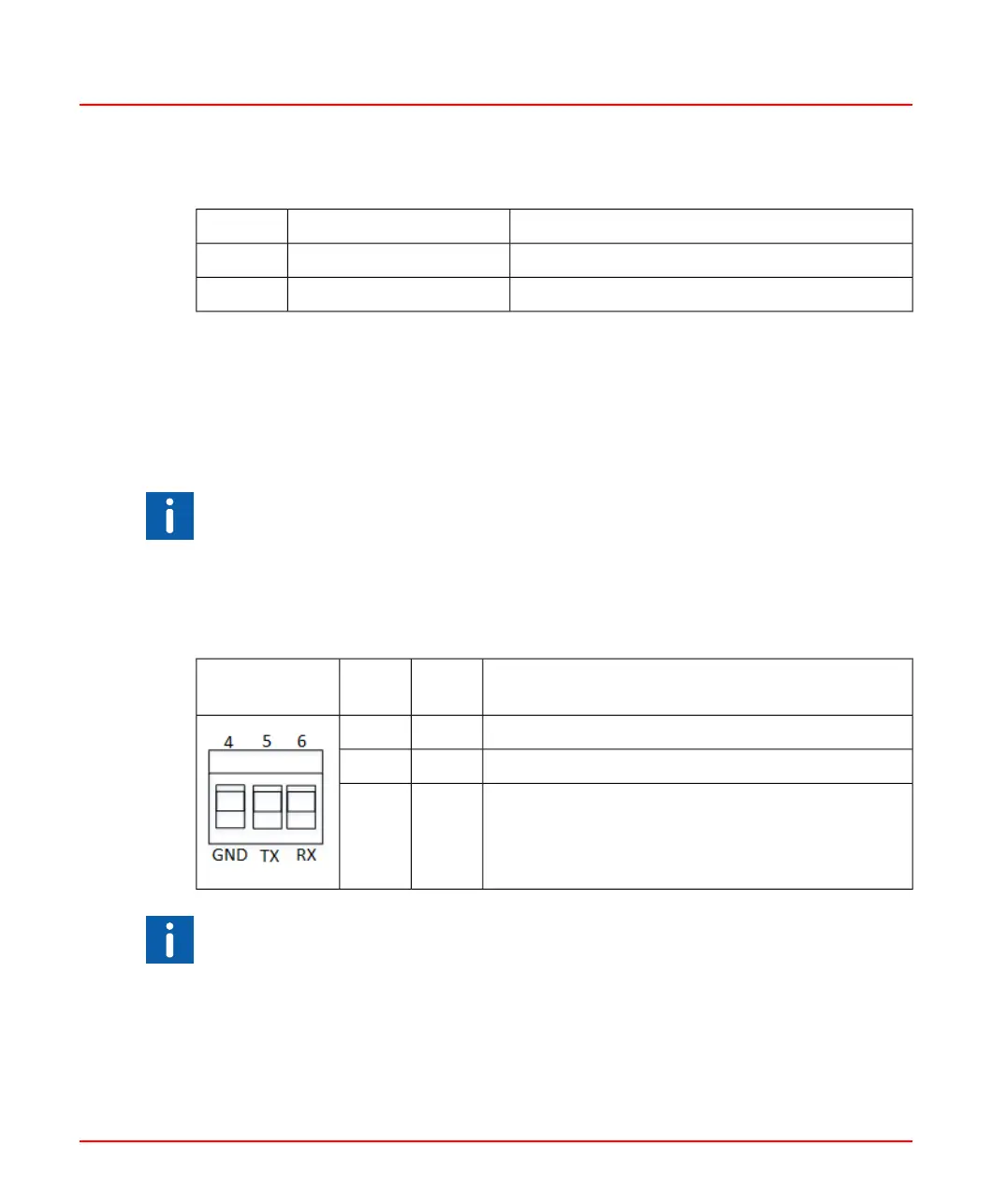
Table 2.8: Redundancy Link Connections
DescriptionSignalPin
Redundancy
Link
GroundGND4
Transmits data to the redundant device.TX5
Receives data from the redundant device.RX6
The receive (RX) and transmit (TX) signals must be crosslinked.
2PAA114135-610 34
2 Hardware Installation
2.4 Mounting and Dismounting

 Loading...


