ACS 400 User’s Manual 37
Note! Alarms (*) will not cause relay output RO1 (RO2) to activate when the relay output is
configured to indicate alarm condition in general. (Parameter 1401
RELAY OUTPUT 1 (1402
RELAY OUTPUT 2) has value 5 (ALARM) or 13 (FLT/ALARM)).
Note! Alarms (**) will be shown only if parameter 1608
DISPLAY ALARMS is set to 1 (YES)
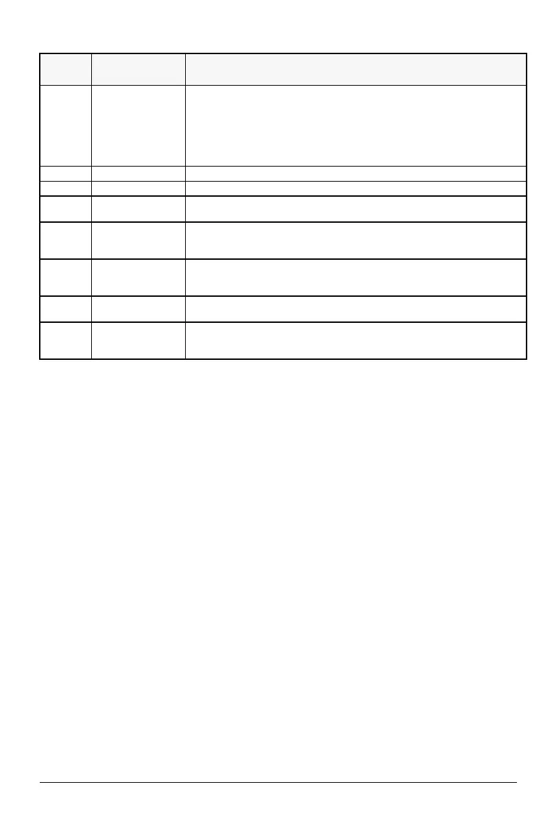
23 DDCS COMM LOSS DDCS communication loss has been detected.
• Check the status of the fieldbus adapter. Refer to the appropriate fieldbus
adapter manual.
• Check the DDCS option module and optical fibers.
• Check connections between the external control system and fieldbus
adapter.
Refer to “DDCS Option module manual” and parameters 5003 – 5006.
24 Reserved.
25 Reserved.
26 **
OUTPUT OVERLOAD Inverter overload condition. The ACS 400 output current exceeds the ratings
given in “Specifications” on page 21 of this manual.
27 *
AUTOMATIC RESET ACS 400 is about to perform automatic fault reset operation. As a result, the
drive may start after the reset operation. Refer to parameter group 31
AUTOMATIC RESET.
28 *
PID SLEEP PID sleep function is active. The drive may accelerate when the PID sleep
function is deactivated. Refer to parameters 4018
SLEEP SELECTION, 4013 PID
SLEEP DELAY, 4014 PID SLEEP LEVEL and 4015 WAKE-UP LEVEL.
29 *
AUTOCHANGE The autochange function of Pump-Fan Control block is active. Refer to
parameter group 81 PFC CONTROL and the appendix for more information.
30
INTERLOCK Pump-Fan Control interlocks are active. The ACS 400 cannot start any motor
(when Autochange is used), or the ACS 400 cannot start the speed regulated
motor (when Autochange is not used).
Alarm
Code
Display Description
http://nicontrols.com
 Loading...


