38 ACS 400 User’s Manual
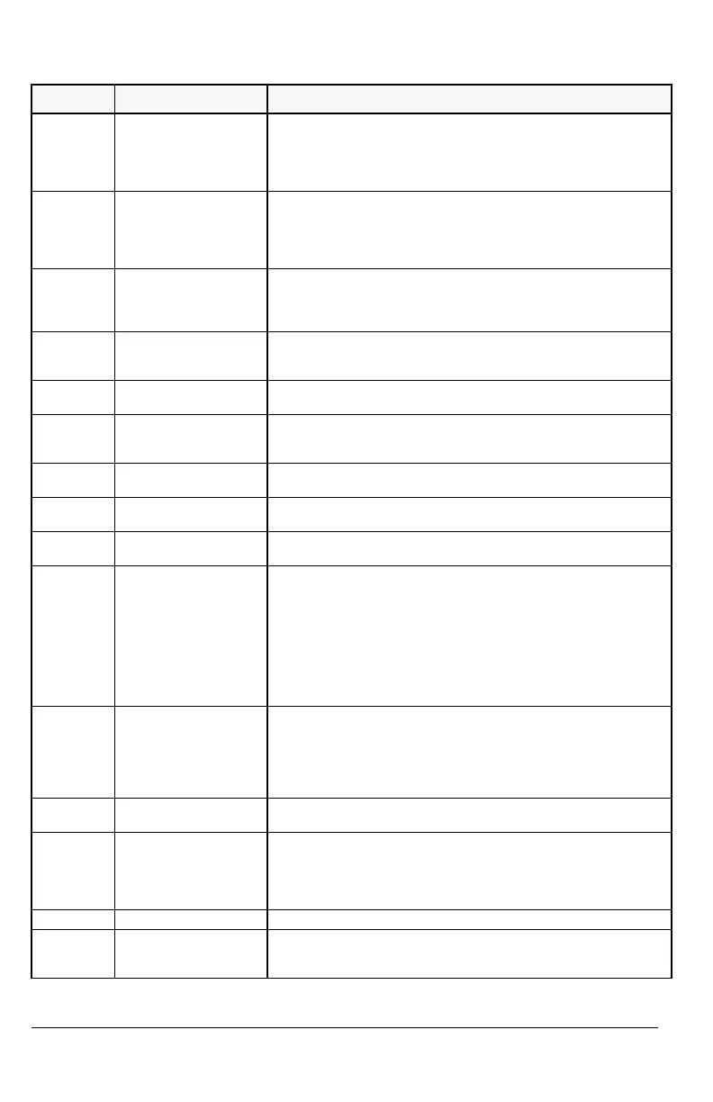
Table 6 Faults.
Fault Code Display
Description
1
OVERCURRENT Output current is excessive.
• Motor load may be too high
• Acceleration time may be too short (parameters 2201
ACCELER
TIME 1 and 2203 ACCELER TIME 2).
• Motor or motor cable is faulty or connected wrong.
2
DC OVERVOLTAGE Intermediate circuit DC voltage is excessive.
• Check the input power supply for static or transient overvoltages
• Deceleration time may be too short (parameters 2202
DECELER
TIME 1 and 2204 DECELER TIME 2)
• Brake chopper (if present) may be underdimensioned
3
ACS400 OVERTEMP ACS 400 heat sink temperature is excessive. Temperature trip limit is
95 °C.
• Check air flow and fan operation.
• Check motor power against unit power.
4 **
SHORT CIRCUIT Fault current. Possible reasons for this fault are:
• There is a short-circuit in the motor cable(s) or motor
• Supply disturbances
5
OUTPUT OVERLOAD Inverter overload condition. The ACS 400 output current exceeds the
ratings given in “Specifications” on page 21 of this manual.
6
DC UNDERVOLTAGE Intermediate circuit DC voltage is not sufficient.
• Input power supply phase may be missing
• Fuse may be blown
7
ANALOGUE INPUT 1 Analog input 1 loss. Analog input value is less than MINIMUM AI1 (1301).
See also parameter 3001
AI<MIN FUNCTION.
8
ANALOGUE INPUT 2 Analog input 2 loss. Analog input value is less than MINIMUM AI2 (1306).
See also parameter 3001
AI<MIN FUNCTION.
9
MOTOR OVERTEMP Motor overtemperature condition as estimated by the ACS 400. Refer
to parameters 3004 – 3008.
10
PANEL LOSS Panel communication loss. Control panel is disconnected when the
drive is receiving start, stop and direction commands from the panel.
- Drive is in local control mode (LOC is shown in the control panel
display), or
- Drive is in remote control mode (REM is shown) and is programmed to
accept start/stop, direction or reference from the panel. Refer to
parameters in groups 10 COMMAND INPUTS and 11 REFERENCE
SELECT.
See also parameter 3002
PANEL LOSS.
11
PARAMETERING Parameter values are inconsistent:
•
MINIMUM AI1 > MAXIMUM AI1 (parameters 1301, 1302)
•
MINIMUM AI2 > MAXIMUM AI2 (parameters 1304, 1305)
•
MINIMUM FREQ > MAXIMUM FREQ (parameters 2007, 2008)
• PFC block tries to use the I/O extension module (NDIO) but the
DDCS link is not programmed properly
12
MOTOR STALL Motor stall. This may be caused by excessive load or insufficient motor
power. Refer to parameters 3009 – 3012.
13
SERIAL COMM LOSS Serial communication through Standard Modbus Channel is lost.
• Check connections between external control system and the
ACS 400.
• Refer to parameters 5003
COMM FAULT TIME and 5004 COMM FAULT
FUNC.
14
EXTERNAL FAULT SIGNAL External fault is active. See parameter 3003 EXTERNAL FAULT.
15 **
OUTPUT EARTH FAULT Ground fault. The load on the input power system is out of balance.
• There may be a fault in the motor or motor cable.
• Motor cable may be too long.
http://nicontrols.com
 Loading...


