Do you have a question about the ABB Excount II and is the answer not in the manual?
Covers legal disclaimers, declaration of conformity, and FCC statements.
Includes important warnings about modifications and notes on device compliance.
Lists registered trademarks of Microsoft Corporation.
Explains the meaning of warning and information symbols used in the manual.
Provides essential safety guidelines for handling and installation of the equipment.
Provides a quick guide for safe and correct installation of the EXCOUNT-II.
Explains how the EXCOUNT-II system measures surges and leakage current.
Details checks to perform when receiving the product and reporting issues.
Lists tools required for installation, noting minimal special tools are needed.
Provides instructions for correctly installing the 9V battery into the transceiver.
Outlines essential steps before sensor installation for trouble-free operation.
Explains sensor power sources and how to install a backup 9V battery.
Guide to installing, uninstalling, and using the EXCOUNT-II software.
Guides through installing USB drivers for the transceiver using the Found New Hardware Wizard.
Details recording sensor and station data and establishing initial PC-sensor links.
Instructs to record sensor ID and related data for registration in the software.
Summarizes four common methods for mounting the EXCOUNT-II sensor.
Advises taking reference measurements after installation and energization.
Detailed steps and diagrams for mounting the sensor on a surge arrester's bottom flange.
Detailed steps and diagrams for mounting the sensor on a planar surface.
Illustrates mounting the sensor on a Transmission Line Arrester (TLA).
Details mounting the sensor on an inverted surge arrester base, including sealing precautions.
Covers environmental conditions, cleaning, and battery replacement for the transceiver.
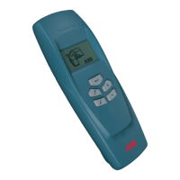
Identifies transceiver buttons and describes how to turn it on/off.
Explains how to connect and use an optional external antenna for improved signal strength.
Provides a key to the symbols displayed on the transceiver screen.
Step-by-step flowchart detailing the process of preparing, making, and transmitting measurements.
Emphasizes synchronizing PC and transceiver clocks for accurate data.
Details the communication range and factors affecting it, including optional external antenna.
Advises keeping the transceiver away from the body to avoid signal interference.
Explains how orientation affects signal strength and optimal pointing directions.
Describes optimal positioning relative to the sensor for maximum signal strength.
Discusses using an external antenna for tall structures like towers and gantries.
Recommends field trials for tower/gantry installations and discusses factors affecting measurement accuracy.
Explains when to use total vs. individual readings and potential issues.
Provides guidelines for scheduling measurements to avoid outages and ensure data accuracy.
Describes how to turn the transceiver on/off and access the main menu options.
Explains options for transferring data between PC and transceiver.
Details how to transfer Sensor IDs from PC to the transceiver.
Details how to transmit collected data from the transceiver to the PC.
Describes how to check the transceiver's battery status and its importance.
Lists measurement types and how to initiate them.
Step-by-step guide to perform leakage current measurements.
Step-by-step guide to read surge counter data.
Instructions for measuring resistive leakage current, noting availability.
Explains how to input operating voltage for resistive leakage current measurement.
Instructions for performing a total reading, noting availability.
Lists options for adjusting transceiver settings.
Instructions for enabling/disabling the transceiver backlight.
Instructions for enabling/disabling the external antenna.
Instructions for adjusting the display contrast.
Guides on setting the transceiver's internal clock and date.
Introduces surge arrester monitoring and its importance for reliability.
Explains the purpose and principle of surge counting for stress indication.
Explains the importance of leakage current for arrester condition monitoring.
Divides leakage current into capacitive and resistive parts and their significance.
Details resistive leakage current, its characteristics, and non-linear behavior.
Explains how harmonics relate to resistive current and diagnostic use.
Describes the EXCOUNT-II's method for measuring resistive leakage current.
Outlines methods for evaluating leakage current levels using manufacturer data.
Details the information provided by manufacturers for arrester analysis.
Explains the packet communication protocol used for error-free data transmission.
Lists technical specifications for surge counting, leakage current, and data communication.
Details general specifications like climatic conditions, temperature range, and power supply.
Discusses the system clock accuracy and temperature dependence.
Provides detailed dimensions for the sensor and external antenna.
Provides instructions for disposing of the EXCOUNT-II components according to local regulations.
Covers system errors, prohibited actions, checksum, and EEPROM issues.
Explains errors related to low/high ambient temperatures for measurements.
Details errors related to field probe and leakage current readings.
Covers unstable current, voltage range, and sensor not found errors.
Explains buffer errors and connection loss during data transmission.
| Brand | ABB |
|---|---|
| Model | Excount II |
| Category | Medical Equipment |
| Language | English |