1MRS 751108-MUM
3URWHFWLRQ5HOD\
Technical Reference Manual, General
5(;
15
2YHUWHPSHUDWXUHLQGLFDWLRQ
The REX protection relay includes an internal temperature supervision function.
The CPU module issues an internal alarm signal when overtemperature has been
detected inside the relay enclosure. The alarm signal will be activated once the
temperature inside the relay enclosure increases approximately to +78
o
C. The
overtemperature indication can be seen on the HMI or as an event via serial
communication. The relay will go to the IRF (internal relay fault) state. See
Table 4.1.11.2-1, “Fault indications,” on page 25.
$QDORJXHFKDQQHOV
The protection relay measures the analogue signals needed for protection,
measuring, etc. via galvanically separated matching transformers. In addition,
current sensors (Rogowski coil) and voltage dividers developed by ABB can be used
with REX 521.
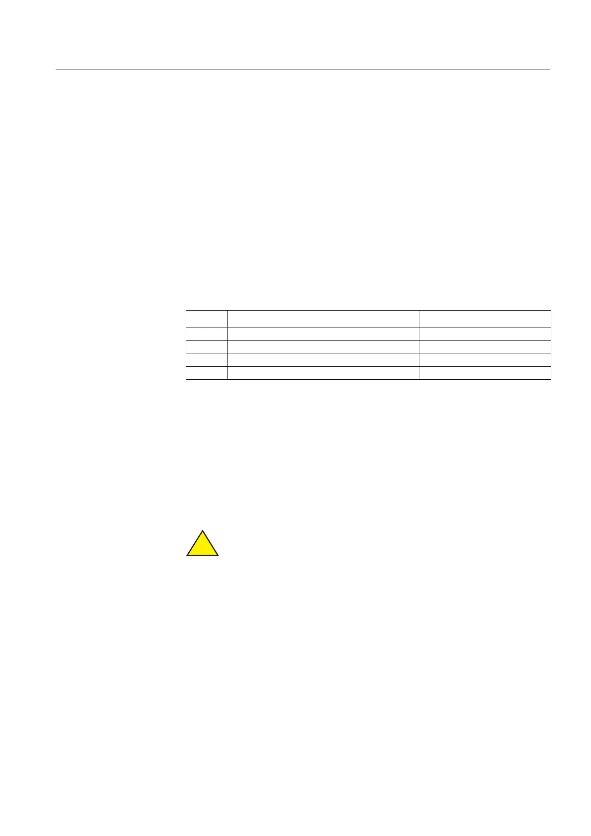
The different versions of REX 521 are provided with the following matching
transformers and sensor inputs:
A letter in the order number specifies whether the protection relay is equipped with
basic, medium, high or sensor measuring input modules. (Refer to section “Ordering
information” on page 48).
6FDOLQJWKHUDWHGYDOXHVRIWKHSURWHFWHGXQLWIRUDQDORJXH
FKDQQHOV
A separate scaling factor can be set for each analogue channel. The factors enable
differences between the ratings of the protected unit and those of the measuring
device (CTs, VTs etc.) The setting value 1.00 means that the rated value of the
protected unit is exactly the same as that of the measuring device.
When scaling factors are used, it should be noted that they affect the
operation accuracy of the relay. The accuracies stated in the description of
each function block (in the CD-ROM
7HFKQLFDO'HVFULSWLRQVRI)XQFWLRQV)
only apply with the default values of the scaling factors. For example, a high
factor affects the operation of sensitive protection functions such as the
directional earth fault protection. To ensure the proper operation of the
function blocks, it must be checked that the analogue scales (pu scales) of
the phase currents I
L1
, I
L2
, and I
L3
, and correspondingly, the analogue scales
of the phase-to-phase voltages U
12
, U
23
, and U
31
or phase-to-earth voltages
U
1
,
U
2
,
and U
3
are identical.
9HUVLRQ 0DWFKLQJWUDQVIRUPHUV 6HQVRULQSXWV
Basic CT1, CT2, CT3, CT4 -
Medium CT1, CT2, CT3, CT4, CT5, VT1 -
High CT1, CT2, CT3, CT4, CT5, VT1, VT2, VT3, VT4 -
Sensor CT4, CT5, VT1 RS1, RS2, RS3, VD1, VD2, VD3
!