18
1MRS 751108-MUM
3URWHFWLRQ5HOD\
Technical Reference Manual, General
5(;
9ROWDJHGLYLGHU
'LJLWDOLQSXWV
The digital inputs of the protection relay are voltage-controlled and optically
isolated. For technical data of the digital inputs, refer to Table 4.2.1-3 on page 37.
)LOWHULQJRIGLJLWDOLQSXWV
The filter time eliminates debounces and short disturbances on digital inputs. The
filter time may be set individually for each input.
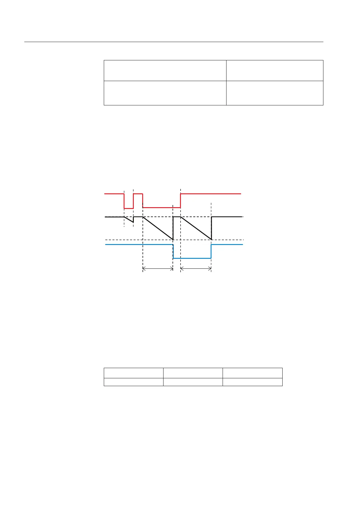
)LJ )LOWHULQJRIDGLJLWDOLQSXW
The figure above illustrates the input filtering. At the beginning, the input signal is
at high state, the first low state is filtered and no input status change is detected. The
second low state is longer than the set filter time, thus detected as a change and
attached with the time tag t
0
.When the input signal returns to high state, after the
filter time, the state is accepted and attached with the time tag t
1
.
Each digital input has a filter time parameter Input # filter
(Configuration\Digital inputs\Input filtering), where # is the
number of the input.
A risk for debounces and short disturbances on digital inputs grows if the input filter
time is changed to less than the default value.
Amplitude error at the whole measuring range
(e = error in per cent)
Amplitude correction factor
= 1/(1+ e/100)
Phase displacement error at the whole
measuring range
(e = error in degrees)
Phase displacement error = - e
7DEOH )LOWHUWLPHSDUDPHWHU
3DUDPHWHU 9DOXHV 'HIDXOW
Input # filter 1...65535 ms 5 ms
t
0
t
1
dipo_rex
Filter Time
Filtered Input
Input
Filter Time
Filter