1MRS 751108-MUM
3URWHFWLRQ5HOD\
Technical Reference Manual, General
5(;
21
7HVWLQJLQSXWVDQGRXWSXWV
The digital inputs and the output relays may be tested using the serial
communication or the HMI.
Generally, the relay has to be in the test mode before the inputs and outputs can be
activated. However, output relays may be activated through the serial
communication without entering the test mode. This is to enable the usage of output
relays for external purposes, not part of the protection and control in the host relay.
The test mode can be set with a parameter. The green READY LED indicator will
be blinking, to announce that the test mode has been entered. In this state, the relay
configuration is disconnected from the physical inputs so that changes on the digital
inputs will not be noticed. When the test mode is deactivated, all test parameters
requiring the test mode, will be reset.
The IRF relay may be tested by using the HMI. The IRF relay testing always requires
entering the test mode.
When testing the general output relays, the user should notice, that normal operation
of the relay cannot be disconnected. If an output relay is permanently activated by
the configuration, it cannot be deactivated for testing.
For further information, refer to
2SHUDWRU¶VPDQXDO (see “References” on page 51).
7ULSFLUFXLWVXSHUYLVLRQ
The trip-circuit supervision consists of two functional units:
• A current limiter including the necessary hardware elements
• A software-based function block, named TCS1
The supervision of the trip circuit is based on the constant current injection principle.
By applying an external voltage over the relay’s trip contacts, a constant current is
forced to flow through the external trip circuit. If the resistance of the trip circuit
exceeds a certain limit, for instance due to a bad contact or oxidation, the supervision
function will be activated and cause a trip-circuit supervision alarm signal after an
adjustable delay time.
Under normal operating conditions, the applied external voltage is divided between
the relay’s internal circuit and the external trip circuit so that at the minimum 20 V
(15...20 V) remains over the relay’s internal circuit. Should the external circuit’s
resistance be too high or the internal circuit’s too low, for example, due to welded
relay contacts, the fault is detected.
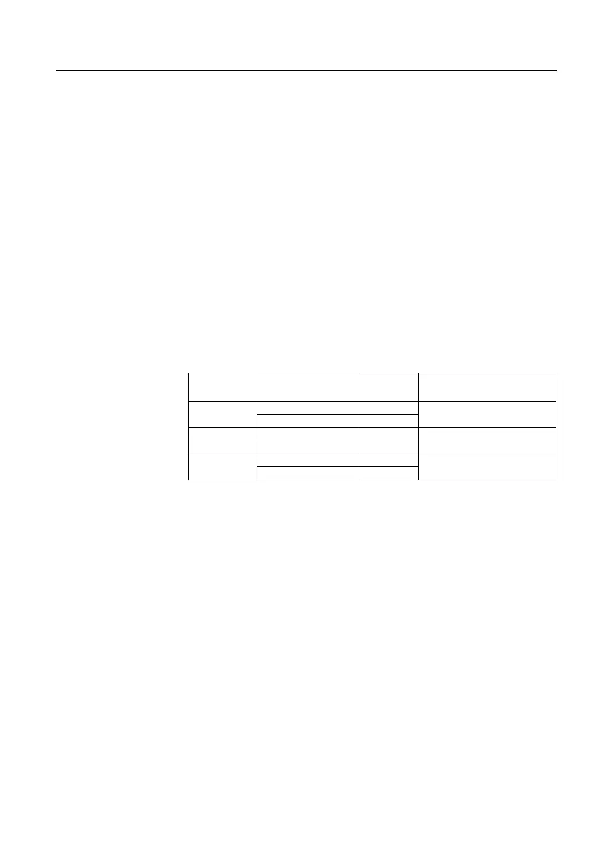
7DEOH 7HVWLQJRILQSXWVDQGRXWSXWV
7HVWREMHFW 8VLQJ
7HVWPRGH
UHTXLUHG
5HPDUNV
Digital inputs HMI Yes Physical inputs disconnected
Serial communication Yes
Output relays HMI Yes Normal operation still active
Serial communication No
IRF relay HMI Yes
Serial communication Yes