26
1MRS 751108-MUM
3URWHFWLRQ5HOD\
Technical Reference Manual, General
5(;
6HULDOFRPPXQLFDWLRQ
The protection relay has two serial communication ports, one on the front panel and
the other on the rear panel.
The connector located on the front panel is a standard ABB optical connector that is
intended to be used for setting the parameters of the protection relay. During the
transmission of the parameters, an interface cable is connected between the relay and
the standard RS-232 interface of a PC, running the Relay Setting Tool.
On the rear panel, there is a fibre-optic interface used to connect the protection relay
to a distribution automation system via SPA, LON, IEC 60870-5-103, or Modbus
bus.
There is also an isolated RS-485 connection (twisted pair) available for SPA and
Modbus communication in connector X3.1:9,10. For the location of the RS-485
connection on the rear panel, refer to “Terminal connections” on page 45. The
connection is marked with texts “Data A” and “Data B” on the panel.
2SWLFDOFRPPXQLFDWLRQSRUWRQWKHUHDUSDQHO
The fibre-optic interface on the rear panel contains two optical connectors, Tx
(X3.2) and Rx (X3.3). The connectors are used for interfacing the unit to an optical
fibre bus using either plastic fibre or glass fibre cables. See also Figure 4.1.12.5.-2
on page 29 for more information about the plastic and glass fibre cables.
The incoming optical fibre is connected to the receiver, input Rx, and the outgoing
optical fibre to the transmitter, output Tx. Special attention should be paid when
handling, mounting and connecting fibre-optic cables. For additional information,
see the document 34 SPA 13 EN1
3ODVWLFFRUHILEUHRSWLFFDEOHV)HDWXUHVDQG
LQVWUXFWLRQVIRUPRXQWLQJ
.
The communication port supports four different protocols, SPA, LON,
IEC 60870-5-103, and Modbus. The SPA, IEC_103, and Modbus protocols are
always supported while LON is not available in all the relay variants. The relay does
not automatically recognize which bus it is connected to and therefore the protocol
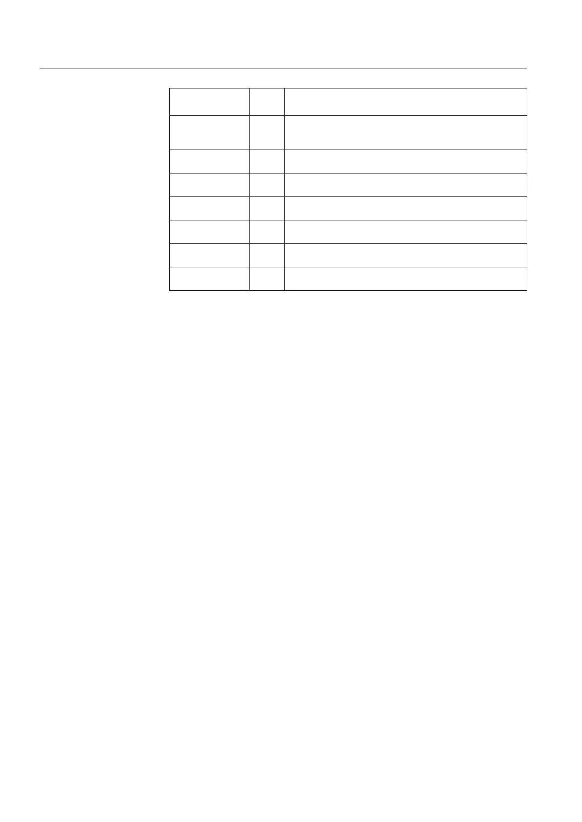
INTERNAL FAULT
Overtemperature
80 Protection operative. The relay has detected an excessive
temperature. May be due to an ambient temperature above
the specified operating limit or an internal fault.
INTERNAL FAULT
Voltage low 24V
131 Protection operative. Output relays do not operate within
specified limits.
INTERNAL FAULT
Volt. high +15V
203 Protection inoperative
INTERNAL FAULT
Volt. high -15V
223 Protection inoperative
INTERNAL FAULT
A/D conversion
253 Protection inoperative
INTERNAL FAULT
Start-up
- Protection inoperative. No communication started, menu
navigation disabled.
INTERNAL FAULT
Unspecified
255 Protection operative or inoperative. The fault location cannot
be determined.
7DEOH )DXOWLQGLFDWLRQV&RQWLQXHG
)DXOWLQGLFDWLRQ
)DXOW
FRGH
5HDVRQ$FWLRQ