11
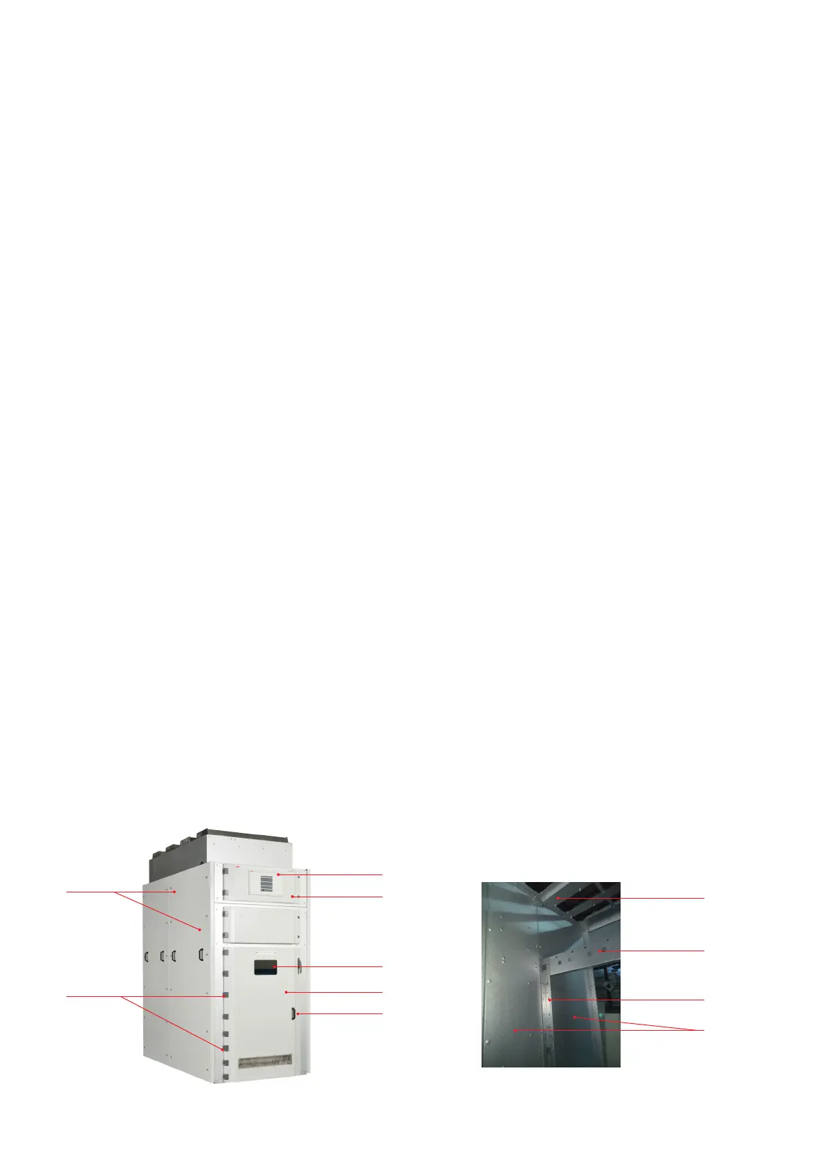
1 Enclosure assembly
2 LV box door
3 Glass window
4 Main panel door
5 Handle
6 Door hinges
7 Side sheets
8 Vertical L support
9 I
s
limiter
TM
fixing steel frame
10 Top channel for support insulator
11 QR6 tripping device
3.5.3 Tripping current transformers
(Figure 3.5)
The tripping transformers 9 are current
transformers which are installed in series with
the I
s
-limiter
TM
and serve to measure the current
flowing through the I
s
-limiter
TM
.
From the outside, the I
s
-limiter
TM
current
transformers cannot be distinguished from
conventional transformers. The particularly
notable characteristics of the special transformer
are:
• an extremely high overcurrent factor
• an iron core with air gap to keep remnant
induction low
• a low resistance shield between the primary
and secondary sides
3.5.4 Tripping device
(Figure 3.1)
The tripping device is installed in the separate
low voltage compartment above the I
s
-limiter
TM
compartment.
For details of the tripping unit type QR6 & Test
Procedure please refer separate manual
GCEA670650 P0102 Rev 01 .
Note: In some cases tripping unit is supplied in
separate floor mounted steel cabinet, depending
on customer requirement & floor space
availability.
—
Fig 3.1a – Panel structure assembly
1
6
11
2
3
4
5
—
Fig 3.1b – Panel enclosure - inside view
10
9
8
7