27
6.6.2 Testing for in-phase condition
Testing of the in-phase condition, e.g. when there
is more than one incoming feeder, can be carried
out with a suitable phase comparator coupled to
the measuring sockets of the capacitive voltage
indication system (if fitted).
Test procedure:
• Only use phase comparators which comply
with the relevant standards and are of
suitable design for the switchgear system.
• Check the function of the unit immediately
prior to use
• Ensure that the maximum permissible length
of the measuring cables for each phase is not
exceeded
• Connect the measuring cables to precisely the
corresponding main conductor sections.
• Follow the directions for the phase
comparator in detail!
6.6.3 Tests on the pulse transformer
No continuity tests may be performed on the
higher voltage side winding (secondary winding)
of the pulse transformer, as otherwise this might
destroy the electronic components cast into the
pulse transformer!
The following operating instructions must also be
observed together with this instruction manual in
the individual cases concerned:
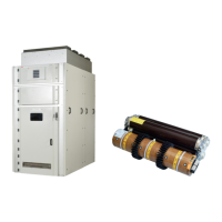
For details of the tripping unit type QR6 & test
procedure please refer separate manual
GCEA670650 P0102 Rev 01
I
s
-limiter
TM
insert: Instruction manual BA 323/04 E
(GCEA 67 0323 P0102)
Customer specific test procedures must also be
referred where ever applicable

 Loading...