8 36KV I
S
LIMITER PANEL INSTALLATION, OPERATION AND MAINTENANCE MANUAL
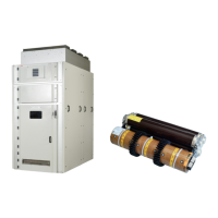
3.1 Basic structure
(Figures 3.1 to 3.4)
The basic design of the panels comprises the
stationary enclosure structure parts made from
Aluzinc sheet.
The I
s
-limiter
TM
holder assembly is fixed inside
panel enclosure on steel frame which is
supported with structure. At the bottom of the
I
s
-limiter
TM
holder assembly copper contacts are
provided for incoming cable connections which
are supported by support insulator on steel
channel which in turn is fixed with panel
structure. At the top side (i.e. outgoing side)
T contact is provided which on one side is fixed
with I
s
-limiter
TM
top contacts & other side of it, the
jumpers are connected.
The outgoing cable connections are provided at
rear side below CT.
Panels with I
s
-limiter
TM
are designed for the
following applications amongst others:
• feeding into existing systems
(transformer or generator feeders)
• coupling between power systems
• bridging of short-circuit current
limiting reactors in transformer or
generator feeders
The I
s
-limiter
TM
panels can be supplemented
by additional panels (circuit-breakers,
disconnectors, cable terminal and surge
arrestor panel)
Further details on the structure of and equipment
in the switchgear can be found in the relevant
order documents.
3.2 Enclosure
The panel enclosure consists of Aluzinc steel
sheets which are rivetted to each other. The roof
of the high voltage compartment is fitted with
integrated pressure relief devices. These devices
open when overpressure occurs as a result of
an internal arc fault. The front is sealed off by
flame- proof doors with hinges at the left and an
opening angle of approx. 180
0
. At rear side, there
are rear covers provided to have access to the
CTs & other components which are mounted at
rear side of the panel. LV compartment containing
the tripping device can be assembled separately
as a self-supporting sheet-steel enclosure.
It is separated and protected from the high
voltage area.
If an internal arc fault occurs, the auxiliary
switches 3, controlling the pressure relief devices
(figure 5.3) achieve I
th
-limitation
by un-delayed release.
The panel doors are made of high quality steel
sheets, which undergo thorough cleaning through
7 tank process before powder coating. The
finishing coat is of standard RAL 7035 color
shade. (Special color shades on request and by
mutual agreement).
3.3 Construction of panels
I
s
-limiter
TM
fixing
(Figures 3.2)
The I
s
-limiter
TM
holders are fixed on the steel
frames with hex. socket cap screws. These two
steel frames are firmly connected with the panel
structure with L type frames at both left & right
side of the panel side walls.
The I
s
-limiter
TM
inserts are inserted in the jaw type
contacts of the insert holder & then clamped
securely with rotating locking levers at top &
bottom of the insert holder.
—
3. Panel structure and components

 Loading...