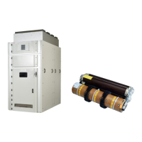
24 36KV I
S
LIMITER PANEL INSTALLATION, OPERATION AND MAINTENANCE MANUAL
Note on safety at work
The relevant work and operating procedures are
to be carried out carefully by trained specialists
familiar with the installation, taking into account
all the relevant safety regulations to IEC and the
other relevant professional bodies, and other
local and works regulations and instructions.
6.1 Commissioning
6.1.1 Preparatory work
In preparation for commissioning, the following
work should be carried out prior to connection
with the high-voltage power supply:
• Check the general condition of the switchgear
for adverse circumstances of all kinds.
• Inspect visually major items like I
s
-limiter
TM
insert fixing in the holder, CTs, insulating
parts, etc.
• Check the connection of the main earthing bar
to the station earthing conductor
(follow the appropriate safety regulations)
• Check the paintwork for damage and touch up
as described in section 7.4, where necessary
• Remove all material residues, foreign bodies
and tools from the switchgear
• Clean the switchgear, rubbing down insulating
parts with a clean, soft, non-fraying and dry
cloth. Remove greasy or adhesive dirt as
described in section 7.3
• Properly refit all covers etc. removed during
assembly and testing processes
• Ensure that all shorting wires/links used while
testing are removed
• Perform AC voltage testing of the main
circuits to IEC 62271-1 as far as necessary. Pay
special attention during this procedure to
voltage transformers, pulse transformers and
cables, etc.
CAUTION!
In order to avoid tripping of the
I
s
-limiter
TM
during the high voltage
and impulse voltage tests, an
insulating disk or cap must be
inserted between telescope contact
and tripping contact 7 (Figure 3.7)
Ensure CT secondary is shorted while
conducting HV test.
After HV test is completed do
remember to remove insulating disk
or cap inserted between telescopic
contacts & tripping device
• Turn the auxiliary and control voltage ON
• Check mechanical and electrical interlocks for
effectiveness, without using force
• Set the protective devices in the switchgear
to the required values and check their
function with test equipment
• When primary current-dependent centrifugal
fans are used, their correct function must also
be tested (see section 7.2)
• For any further questions on the functions of
the I
s
-limiter
TM
switch and its testing,
see section 7.5
• Instruct the local operators in the
fundamental details of regular handling of the
switchgear
• Check the readiness for operation and
switching status of electrical systems
upstream and downstream from the
switchgear
Depending on the allocation of responsibilities,
it may also be necessary to check the following
equipment in areas adjacent to the switchgear:
• power cables
• auxiliary cables
• auxiliary power source
• remote control system
• complete earthing system
• switch room equipment
• switch room condition
—
6. Commissioning/Operation

 Loading...