January 2019 KPM KB2 Man W41100099V1.8 7
5) Connect the conduit to the sensor head tube. After that you can install the sensor head tube
to its measuring position. The sensor should be installed about 25 cm (10") inside from the
edge of the web and 15 cm (6") below or above it. Standard range is 10 -
30 cm (4 - 12").
Continue the installation as follows:
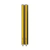
6) Install the mounting clamps (Fig. 2.8) or the rack (optional, Fig. 2.9) or PosiEye adapter
(optional, Fig. 2.10) on paper machine’s frame or other solid mounting structure. Leave 20 -
30 cm (8 - 12") between the clamps. It is recommended to leave option to adjust clamp height
so that sensor head can be positioned optimally during the start-up.
Fig. 2.8. Mounting clamps.
Fig. 2.9. Mounting rack (option).
Fig. 2.10. PosiEye adapter.
NOTE
There is several lengths of the PosiEye Tube, with the longest tubes, the sensor head adapter
needs to be flipped around so that it goes inside the PosiEye tube.