8
7) Connect fiber optic cable to the display unit, see paragraph 2.4.
8) Slide the sensor tube through the mounting clamps. Rotate the eyes into a position towards
the web and semi-tighten the clamps. Final adjustment is done with the help of the signal
level display after the unit is powered up. The light beam is directed to the measured web.
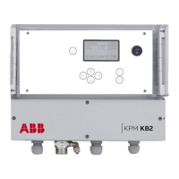
9) Insert the pin of the position memory ring (Fig. 2.11) into the hole in the clamp and tighten
the stop screw. If the sensor is removed for maintenance the memory ring ensures that the
sensor head is positioned exactly in the same position as before the removal. Adapters for
PosiEye installations are available.
Fig. 2.11 Position memory.
Fiber optic cable installation
NOTE
Handle fiber optic cables with care. Do not pull strongly. Remove protective caps before
connecting to the optic block.
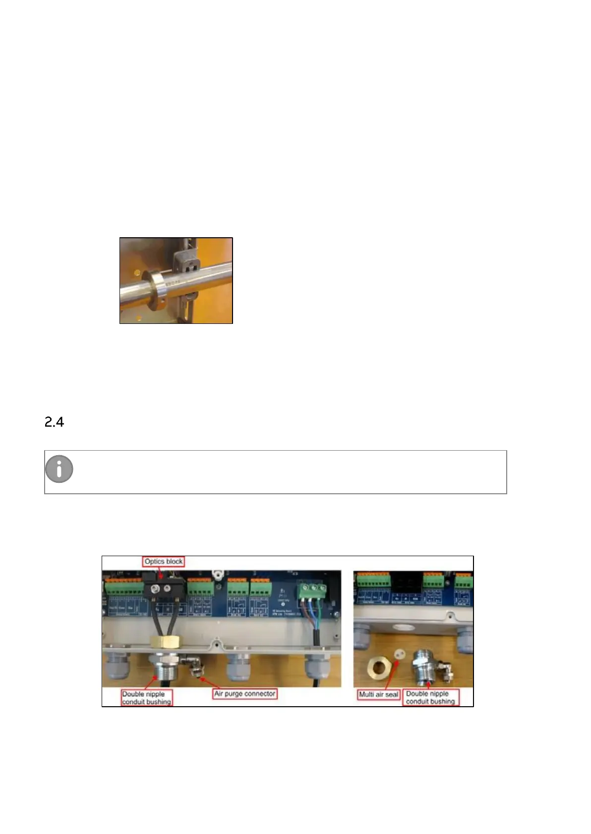
Route the flexible conduit with the fiber optic cable inside it to the display unit.
1. Remove the conduit bushing from the display unit.
Fig. 2.12. Removing the conduit bushing from the display unit.