January 2019 KPM KB2 Man W41100099V1.8 9
2. Guide the end of the fiber optic cable through the conduit bushing and fasten the bushing
to the flexible conduit.
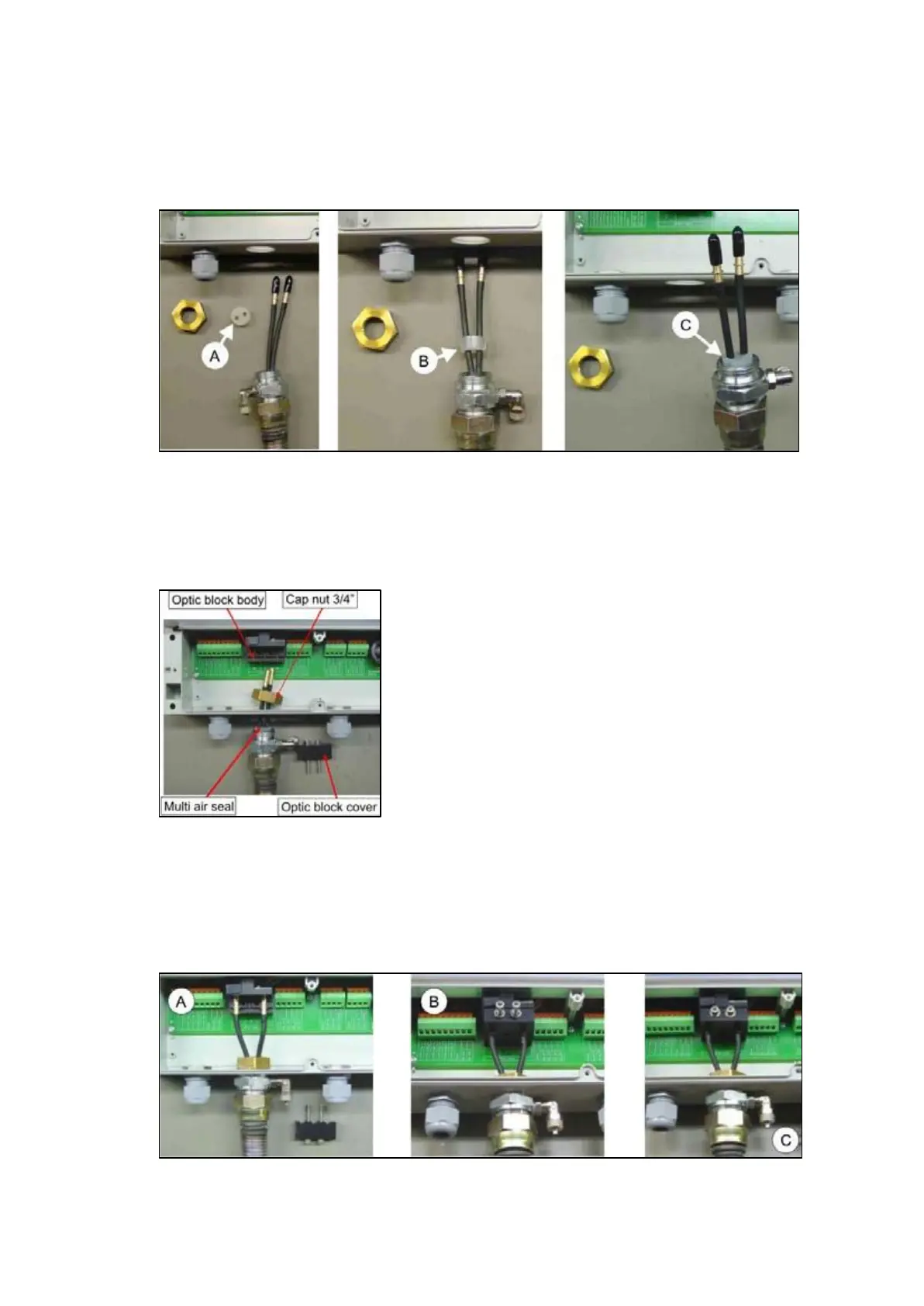
3. Place the multi air seal on top of the fiber optic cables, Fig. 2.13, points A & B.
4.
Insert the multi air seal inside the conduit bushing, step C.
Fig. 2.13. Multi air seal inserting.
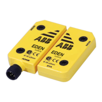
5. Open the optics block cover, slide the cables through the bushing hole, cap nut and
tighten the bushing loosely, Fig. 2.14.
6. Insert one of the cables to the Rx slot and the other one to the RGB slot (or to IR slot if IR
light is used). It does not matter which one of the cables is connected to the Rx slot.
Fig. 2.14. Connecting cables to optical unit.
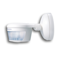
7. Lock the cables in place with the optic block cover, Fig. 2.15, points A & B.
8. Fasten the optic block cover and tighten the cap nut of the cable bushing, points B & C.
9. Connect the instrument air 0.5 - 3.0 bar (7 - 40 psi) to the air inlet connector (point C) at the
end of the flexible conduit outside the display unit housing.
Fig. 2.15. Connecting cables to optical unit.