10
3 Wiring
Wiring and fiber optic cable connection
The terminals for the electrical and fiber optic cables are located under the bottom cover of the
display unit.
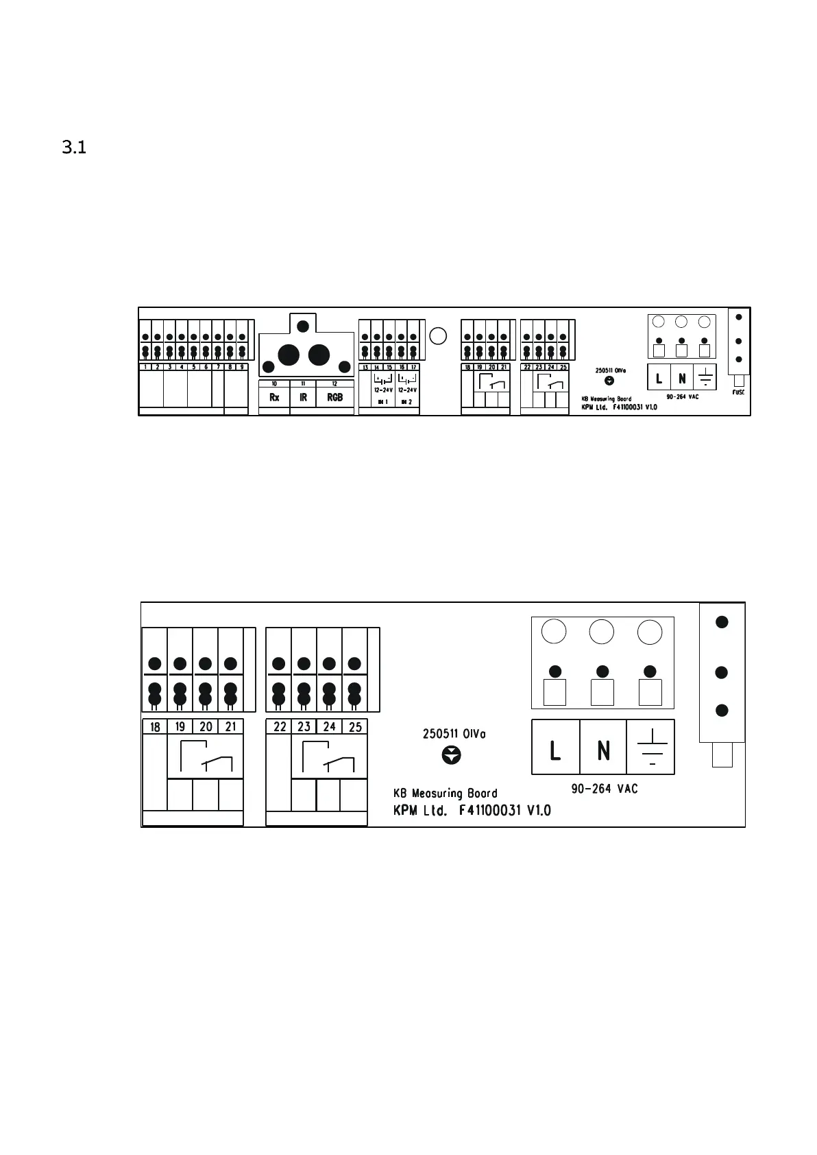
3.1.1 KPM KB2 with 110 – 230 VAC + power supply
The layout of the KPM KB2 110 – 230 VAC measuring board is shown in Fig. 3.1.
Fig. 3.1. KPM KB2 110 – 230 VAC measuring board layout.
Relays are of dry contact types. In normal operation the "Break Out On" relay is open and it closes
during a break. In case the power is lost or turned off the "Break Out On" relay remains open
(disabled). "Break Out Off" works in the opposite way.
”Alarm Out Off" is normally closed. It opens in case the built-in self-diagnostics detects a failure.
If power is lost or turned off the "Alarm Out Off" is OPEN. "Alarm Out On" works in the opposite
way.
Fig. 3.2. KPM KB2 110 – 230 VAC. Wiring of Power Supply, Break relay and Maintenance alarm.