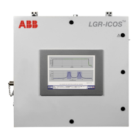
GLA531 Series LGR-ICOS™ Gas Analyzer
Operating Manual
3KXG165002R4201_2021_04
ABB PROPRIETARY INFORMATION 36
NOTE
All signal-cables for data transfer and communications (Ethernet, Modbus, and
4-20 mA) require true metallic shielding for EMI protection.
Ethernet
The ABB GLA531 Series LGR-ICOS™ Gas Analyzer runs on the UNIX operating system. Data files stored on
the internal hard drive of the analyzer can be accessed via a Windows Share Drive over a local area network
(LAN) Ethernet connection. For the Ethernet feature to work, the analyzer must:
• Be connected to a LAN via the RJ-45 Ethernet connection through a suitable cable gland located on the left
side of the analyzer enclosure.
• Receive a response to a Dynamic Host Configuration Protocol (DHCP) request when the analyzer is
initialized. If the analyzer does not receive a reply, it will:
o Disable the Ethernet port
o Not attempt another DHCP request until the analyzer is restarted.
When the above conditions are met, the data directory can be accessed using a Windows computer on the same
LAN. To access the Windows Share Drive:
STEP 1 Select Start à Run, then type: \\YYMMxxxxxxxx (Instrument Serial Number).
STEP 2 Press Enter.
After the communication link is established, a Windows Share Drive directory window appears as
subdirectory lgrdata.
STEP 3 Double-click the lgrdata directory to display the data files stored on the internal hard drive.
STEP 4 Open or transfer any of the data files as you would with any other Windows Share Drive.
Modbus/TCP
A Moxa application CD (P/N: 1112012001031) with the associated instructions are shipped with each ABB
GLA531 Series LGR-ICOS™ Gas Analyzer to support the ioLogik E1240 Modbus: This lets you link and
configure the Modbus to the desired format. Modbus outputs are the gas concentration measured and the
warning/fault signals. The Modbus analog inputs are described in Table 5 below.

 Loading...