13
—
08
—
09
—
10
—
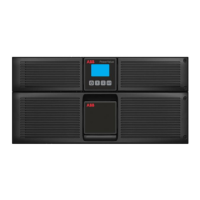
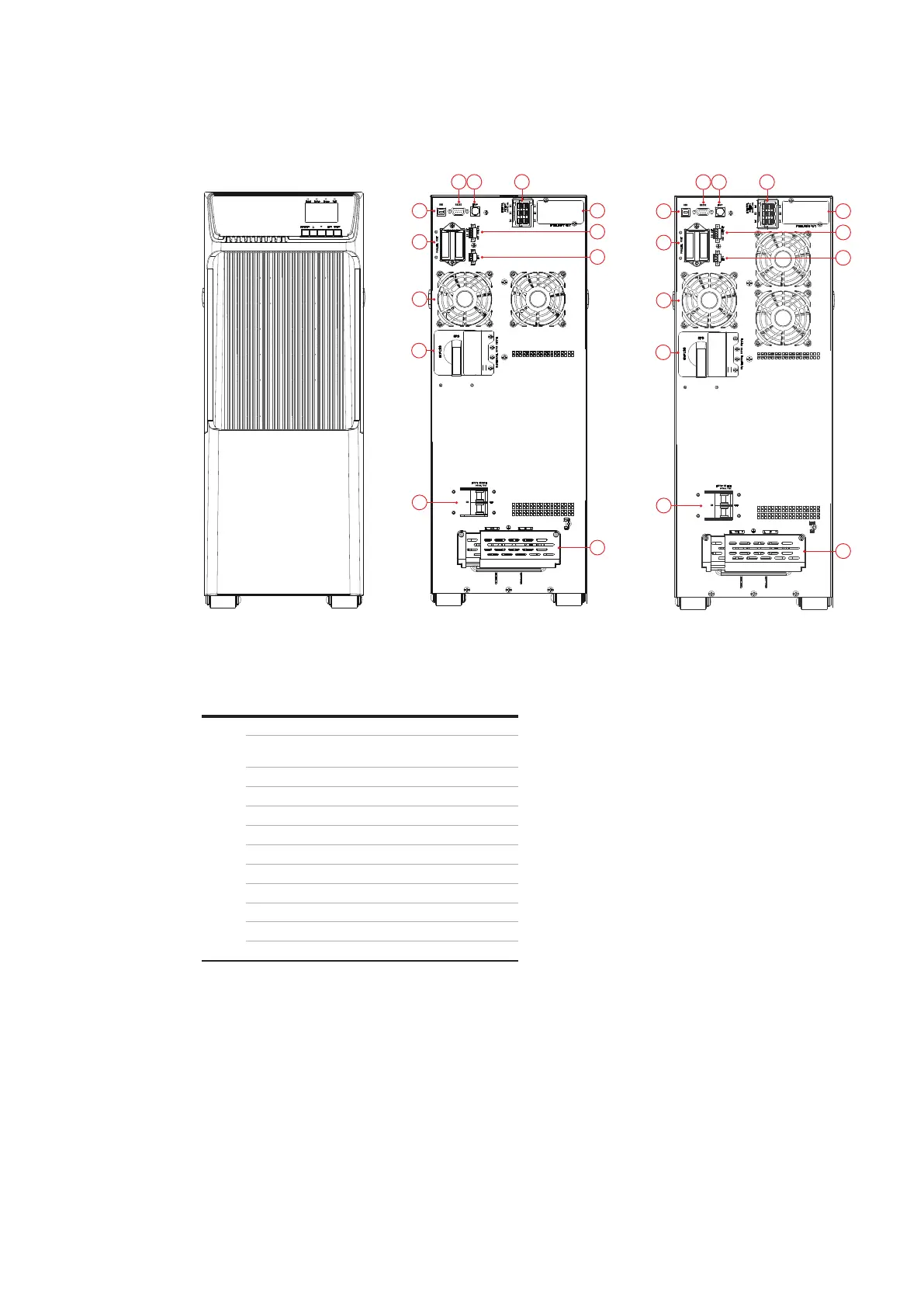
Table 3: UPS 6-10kVA B/B2 model front and
rear panel connectors and ports
[reserved for future development]
EBM connector
USB
Dry IN/OUT
Parallel card
EPO
Fans
Maintenance bypass switch
Input switch
Input/Output terminals
3 INSTALL ATION
3.3.2 UPS 6-10 kVA B/B2
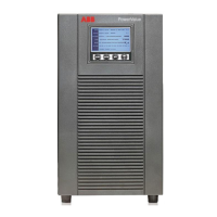
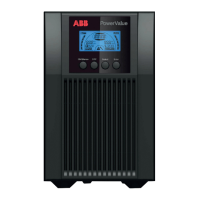
The figures below shows the front and the rear
panel of the UPS 6-10 kVA B/B2 model.
—
08 UPS front panel
—
09 UPS 6 kVA B/B2
rear panel
—
10 UPS 10 kVA B/B2
rear panel
4
21 3
5
7
6
8
9
10
11
12
4
21 3
5
7
6
8
9
10
11
12
 Loading...