Operation Manual / Power2 340-H / High-pressure stage
9 Disassembly and assembly / 9.8 Installing the cartridge group
© Copyright 2022 ABB. All rights reserved. HZTL4054_EN Rev.F March 2022
9.8 Installing the cartridge group
Nozzle ring compression
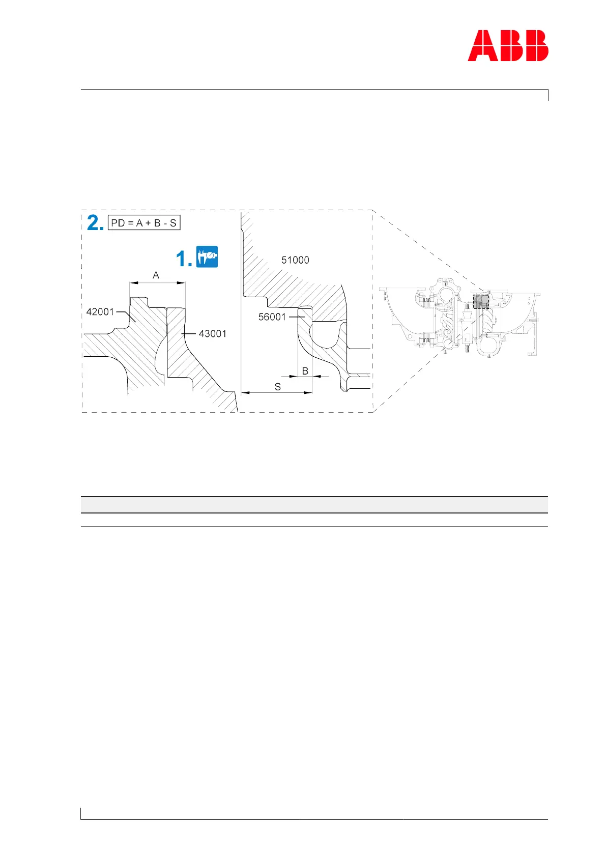
In order for the nozzle ring (56001) to be fixed during operation, it must be clamped
between the heat shield(43001) and the turbine casing(51000).
Fig.34: Nozzle ring compression PD
42001 Bearing casing
43001 Heat shield
51000 Turbine casing
56001 Nozzle ring
Compression PD
0.09 ... 0.31mm
Table42: Nozzle ring compression PD
1. Measure dimensions A, B, and S on cleaned surfaces.
2. Calculate compression (PD).
u If the calculated value(PD) lies outside the specified range, contact a Turbo Systems ser-
vice station.
Page 79 / 114