Operation Manual / Power2 340-H / High-pressure stage
1 Introduction / 1.5 Layout and function of the high-pressure stage
© Copyright 2022 ABB. All rights reserved. HZTL4054_EN Rev.F March 2022
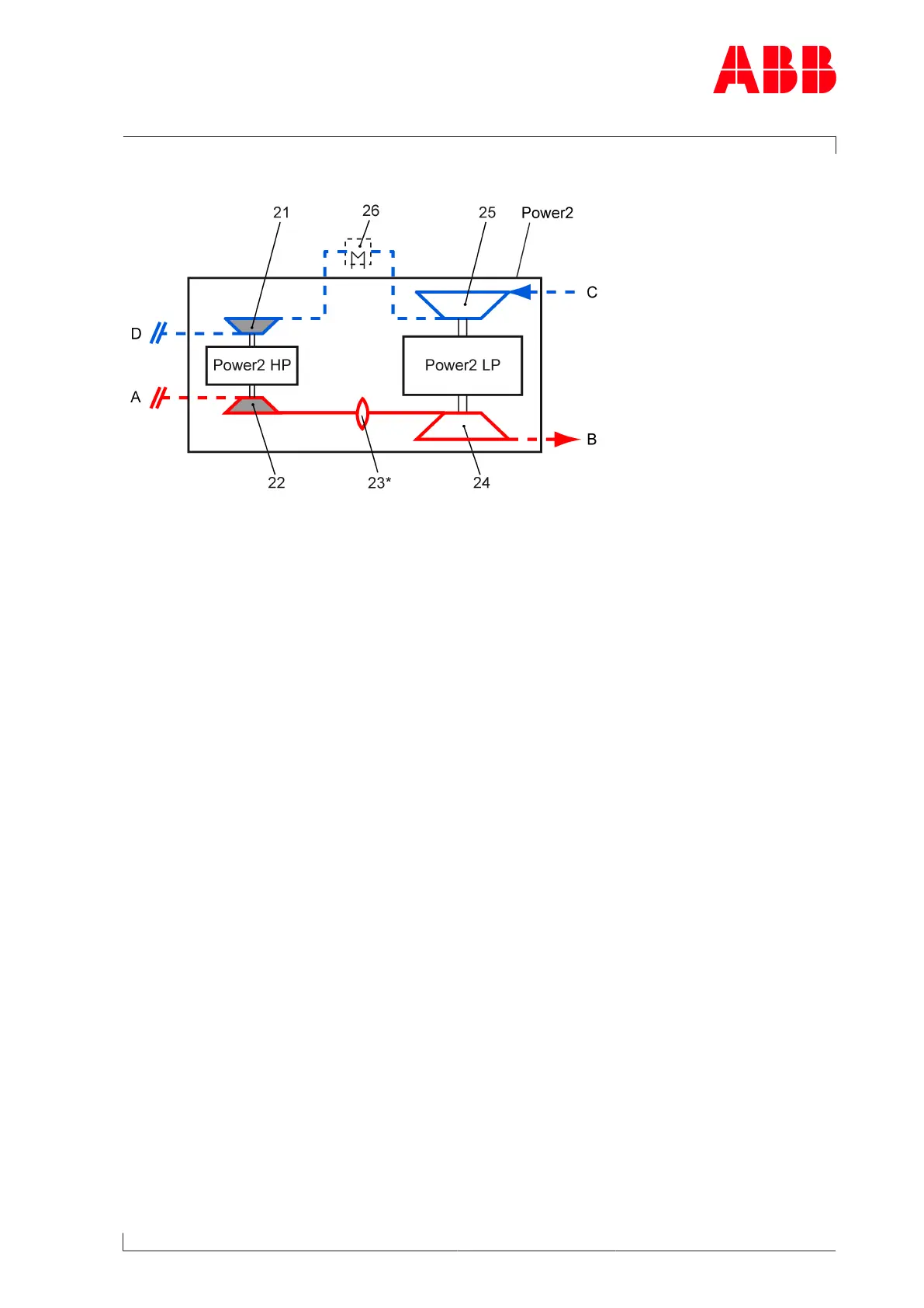
Mode of operation of the high-pressure stage (Power2 HP)
Fig.3: Function of the high-pressure stage
Power2 Two-stage turbocharging 21 HP compressor
Power2 LP Low-pressure stage 22 HP turbine
Power2 HP High-pressure stage 23* Gas piping (bellows)
A Exhaust gas inlet from internal combus-
tion engine
24 LP turbine
B Exhaust gas outlet 25 LP compressor
C Air or air/gas mixture inlet 26 Intercooler
D Air or air/gas mixture outlet and supply
to the charge air cooler
- - - Not included in the Turbo Systems
scope of delivery
*) If present
The high-pressure stage (Power2 HP) is a turbomachine, and its main components are a tur-
bine and a compressor. These components are installed on a common shaft and form the ro-
tor (see Fig.2: Layout of the high-pressure stage →8).
In the high-pressure stage(Power2 HP) shown in the sectional view (see Fig.2: Layout of the
high-pressure stage →8), the exhaust gas flows through the turbine casing(14) and the
nozzle ring(11) and reaches the turbine(08). The HP turbine uses the energy contained in the
exhaust gas to drive the rotor. The exhaust gases then flow through the gas outlet flange
(10), the gas outlet casing (09) and the exhaust gas pipe connected to it before they reach
the turbine of the low-pressure stage (Power2 LP).
The rotor runs in two radial plain bearings (07), which are located in the bearing casing(06)
between the compressor and turbine. The axial thrust bearing (05) is located between the
two radial plain bearings. The plain bearings are connected to a central lubricating oil duct
which is normally supplied by the lubricating oil circuit of the engine. The oil outlet lies at the
deepest point of the bearing casing.
The HP compressor wheel(16) connected to the shaft sucks in the precompressed air or an
air/gas mixture from the low-pressure stage(25) through the air suction branch(01). The air
is compressed further in the HP compressor(21) and the downstream diffuser(04) and sub-
sequently supplied to the charge air cooler via the compressor casing(03).
Page 9 / 114