64 Product manual - PVS-175-TL;A.1 Version
EN
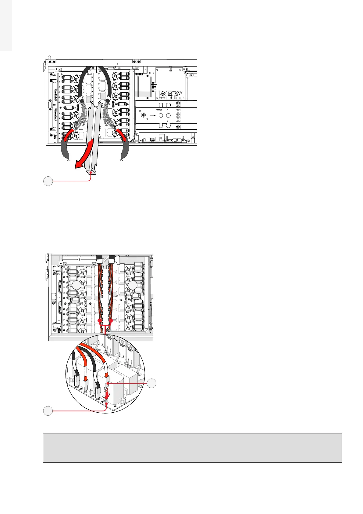
• Remove the cable sheathing from the DC interface cables (33) and the DC cable duct (22) from the DC
surge arrester plate (21).
22
• Connect all DC interface cables (33) to the related DC interface faston connectors (29) located in the DC
surge arrester plate (21).
The two cable group are marked with a identification label “B1” and “B2” that corresponds to the DSP
board number label (“B1” and “B2”).
Each single cable are marked with a label corresponding to related DC interface faston connectors (29)
on the DSP boards (E.g. “TB1”, “TB3”...).
B2
B1
29
33
WARNING – B Polarity inversion can cause serious damage. Check polarity before connecting
each cable!
WARNING – B Always check correspondence of cables and board faston connectors identification!