- 81 -
000872BG
5 - Installation
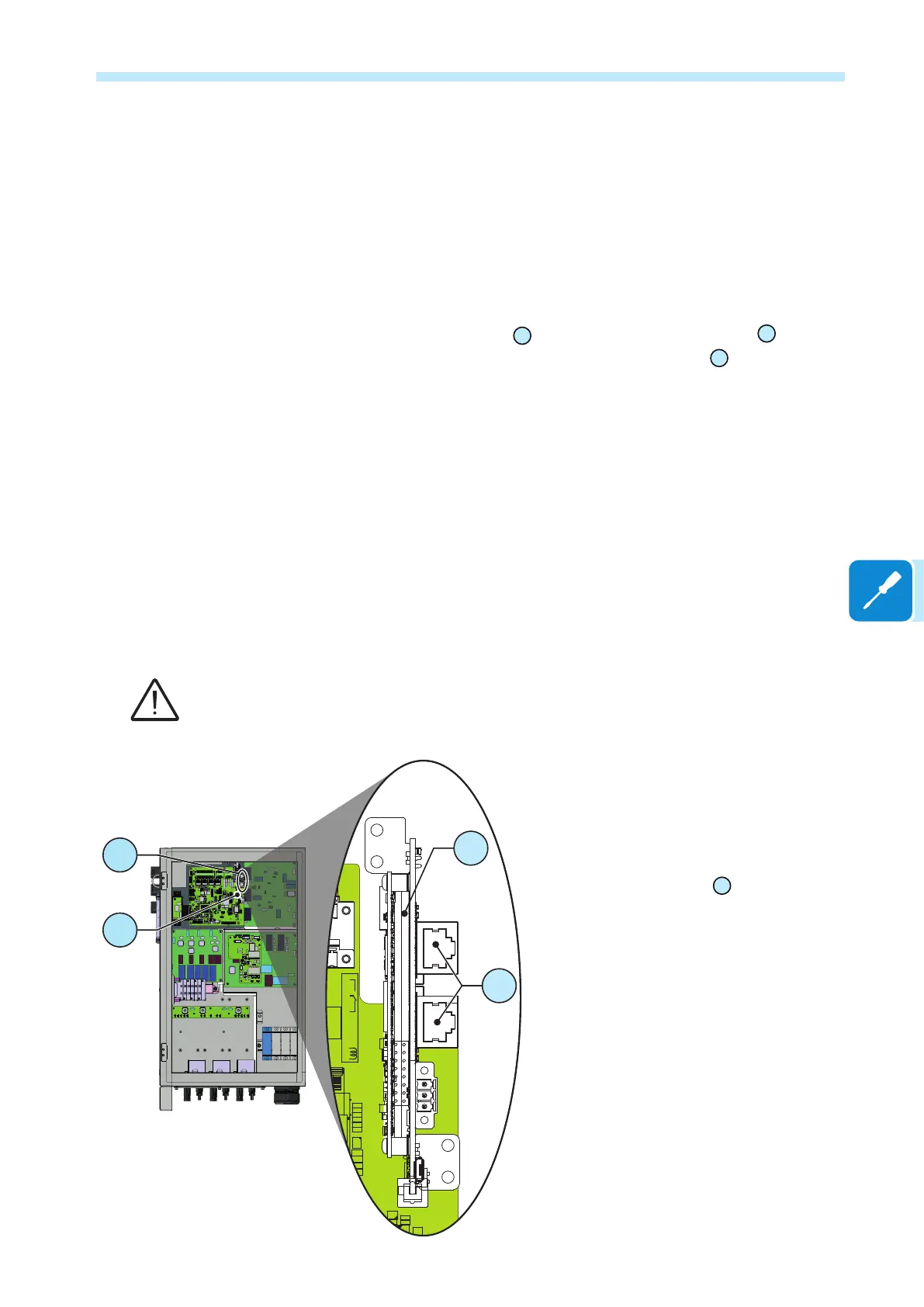
Ethernet connection
The ethernet connection allows a direct data transfer to the ABB server
for monitoring purpose.
When the inverter will be powered on, network parameters are
automatically set and the inverter start transmissing telemetry data to the
Aurora Vision
®
CLOUD platform.
The connection of the ethernet communication cable must be made on
the specic connectors
65
located on the interposer board
50
(vertically
positioned on the communication and control board
35
)inside the wiring
box. If the inverters of the plant need to be connected in daisy chain or ring
conguration use both connectors.
The cable should be compliant to the following specication:
• Cable type: Patch or Cross type, 100BaseTx, CAT5e (or higher) with
shielding STP or FTP.
• UV-resistant if used outdoors
• Type of plug: metallic shielded RJ45
• The maximum length that can reach these cables is 100 meters, and
it is always advisable not to let them pass by the power cords to avoid
interference with data transmission.
• Maximum inverters number connected over one single daisy chain is 40
In order to avoid ground loop (that could create communication issues) the shield of any
Ethernet cable must be connected to the RJ45 plug in only one side, the other side of the
shield should be leaved oating. This could be guaranteed by crimping the shield or the screen
of the ethernet cable to the RJ45 connectors only at one end of each cables.
Connection of ethernet cable is made trought
the two RJ45 connectors
65
.
The two RJ45 connectors are equivalent to
each other and can be used interchangeably
for the input or for the output of the line in
realising the connection of the inverters.
50
65