- 80 -
000872BG
5 - Installation
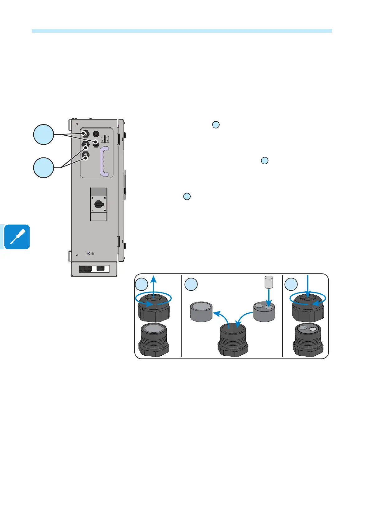
Connections to the communication and control board
The communication and control signals are connected to the
communication and control board inside the wiring box. in particular, on
the left side of the DC wiring box, there are:
- 2 ethernet cable glands
12
(one PG21 and one PG16). The two
cable glands can be used for the daisy-chain connection (in / out) of
inverters present on the system. The ethernet connection can be used to
monitor, congure, and update the rmware remotely and is made on the
dedicated connectors on the interposer board
50
.
- 2 cable glands
13
(PG21 ) that can be used to reach the terminals
/ connectors on the communication and control board. Each
cable gland accepts a cable (from 13 mm to 18 mm diameter).
As an alternative to each cable gland, the two-hole gasket (supplied) can
be installed, which accepts two cables with a diameter of 1.5 to 6mm; If
a seal hole is not to be used, it is necessary to install a plug (supplied
plastic cylinder) to ensure the inverter’s sealing.