- 53 -
000866BG
5 - Installation
Installation site and position
• Consult the technical data to check the required environmental condi-
tions (protection rating, temperature, humidity, altitude, etc.)
• Installation of the unit in a location exposed to direct sunlight is acceptable.
Except for the version equipped with a display.
• Do not install in small closed rooms where air cannot circulate freely
• Always ensure that the ow of air around the inverter is not blocked so
as to prevent overheating.
• Do not install near ammable substances (minimum distance 3 m)
• Do not install on wooden walls or near ammable substances.
• Do not install in rooms where people live or where the prolonged pre-
sence of people or animals is expected, because of the high noise that
the inverter produces during operation The level of the sound emission
is heavily inuenced by where the appliance is installed (for example:
the type of surface around the inverter, the general properties of the
room, etc.) and the quality of the electricity supply.
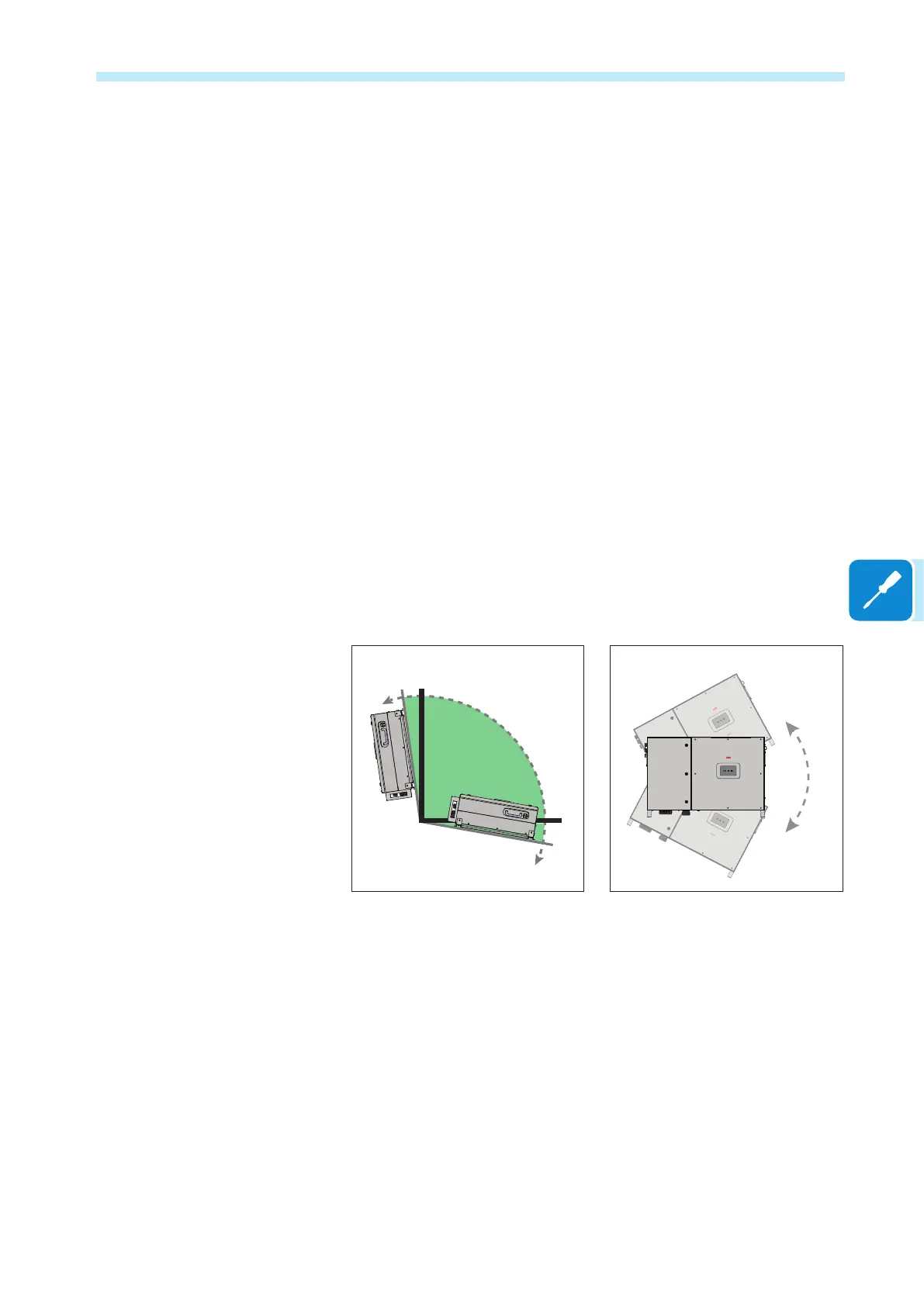
• Installation of these models can be carried out vertically or horizontally,
with a maximum inclination as indicated in the gure.
NO
NO
OK OK OK
PVS-60 PVS-60 PVS-60
OK
OK
OK
PVS-60
PVS-60
PVS-60
NO NO
PVS-60 PVS-60
OK OK
PVS-60 PVS-60
PVS-60
PVS-60
5° MAX
OK
NO
NO
OK OK OK
PVS-60 PVS-60 PVS-60
OK
OK
OK
PVS-60
PVS-60
PVS-60
NO NO
PVS-60 PVS-60
OK OK
PVS-60 PVS-60
PVS-60
PVS-60
5° MAX
• Hardware and software maintenance on device entails opening the front
cover. Check that the correct installation safety distances are observed
in order to allow routine check and maintenance operations.
• Install on a wall or strong structure suitable to bear the weight
• If possible, install at eye-level so that the status LEDS can be seen
easily.
• Install at a height which takes into consideration the weight of the ap-
pliance and in a position which is suitable for servicing, unless suitable
means are provided to carry out the operation
• Final installation of the device must not compromise access to any dis-
connection devices that may be located externally.



 To Next Page