- 85 -
000872BG
5 - Installation
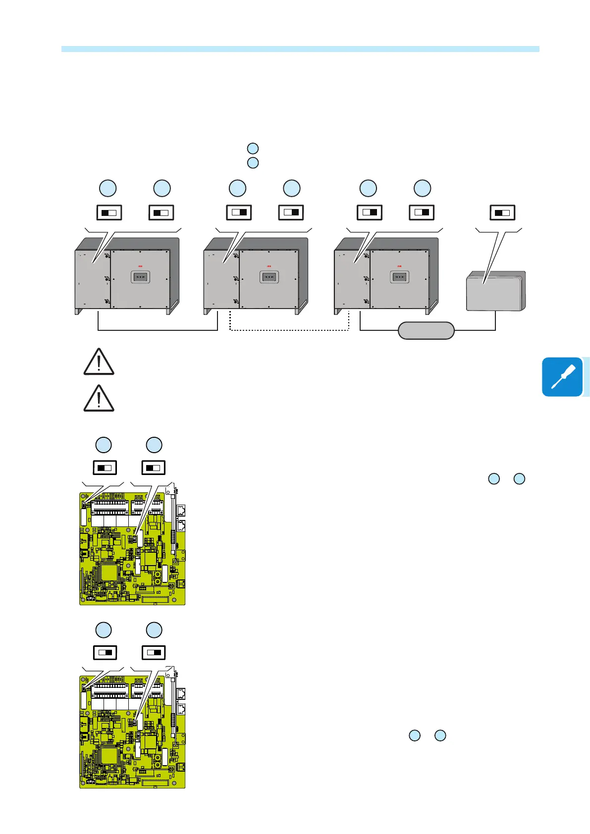
For both type of connection, proceed to connect all the units of the
RS485 chain in accordance with the daisy-chain model observing the
correspondence between the signals, and activate the termination
resistance of the communication line in the nal element of the chain by
switching:
- the
54
switch for the RS485-1 line in the ON position.
- the
58
switch for the RS485-2 line in the ON position.
PVS-60 PVS-60 PVS-60
Monitoring
system
ON
S6
RS485-1 120Ω
ON
ON
120
Ω
TERM.
RS485
DC DC DC
54
S5
RS485-2 120Ω
58
OFF
S6
RS485-1 120Ω
OFF
54
S5
RS485-2 120Ω
58
OFF
S6
RS485-1 120Ω
OFF
54
S5
RS485-2 120Ω
58
The communication line must also be terminated on the rst element of the chain which
normally corresponds to the monitoring device.
It is recommended not to exceed a length of 1000m for the communication line.
The maximum number of inverters that can be connected to the same RS485 line is 62.
When connecting a single inverter to the monitoring system, activate the
communication line resistance terminal by setting the switch
54
or
58
(to
the ON position).
Set a different RS485 address on each inverter in the chain. No inverter
can have “Auto” as an address. An address can be freely chosen
between 2 and 63.
The setting of the address on the inverter is done through the "Aurora
Manager" software.
When an RS-485 connection is being used, if one or more inverters are
added to the system at a later time, it is necessary to remember to reset
to OFF the switch on the termination resistance being used (1) or (2) on
the inverter which previously was the last in the system.
Each inverter is shipped with the RS485 address pre-set to two (2) and
with the resistance terminal setting switch
54
or
58
in the OFF position.
J1
J18
J8
X5
J9 J10 J11 J12
J16
A5
J14
J13
S6
J20
J17
J21
J7
J18
J2
S5
S7
J5
J24
K5
S9
S8
T5
J27
J6
J19
J22
K6
J25
J15
J3
8
9
0
5
6
7
NCCOM
NO
NCCOM
NO
1
2
3
4
1
2
3
4
8
9
0
5
6
7
OFFON
PC2
OFFON
PC1
J1
J18
J8
X5
J9 J10 J11 J12
J16
A5
J14
J13
S6
J20
J17
J21
J7
J18
J2
S5
S7
J5
J24
K5
S9
S8
T5
J27
J6
J19
J22
K6
J25
J15
J3
8
9
0
5
6
7
NCCOM
NO
NCCOM
NO
1
2
3
4
1
2
3
4
8
9
0
5
6
7
OFFON
PC2
OFFON
PC1
ON ON
S6
RS485-1 120Ω
54
S5
RS485-2 120Ω
58
S6
RS485-1 120Ω
54
S5
RS485-2 120Ω
58
OFF
OFF