97
Description HR/IR address
(.bit)
DI/Coil bit
address
Writeable Value range Comment
Number of AR shots (shot 2) initiated
by the start or trip signal from stage I
0
>
825 0...255 Counter
Number of AR shots (shot 3) initiated
by the trip signal from stage I>>
826 0...255 Counter
Number of AR shots (shot 3) initiated
by the digital input signal
827 0...255 Counter
Number of AR shots (shot 3) initiated
by the start or trip signal from stage I>
828 0...255 Counter
Number of AR shots (shot 3) initiated
by the start or trip signal from stage I
0
>
829 0...255 Counter
Table 5.1.15.1.-13 Mapping of Modbus data: control points
Description HR/IR address
(.bit)
DI/Coil bit
address
Writeable Value range Comment
LED reset 501 W 1 1 = LED reset
a)
a)
Coil area, only writeable.
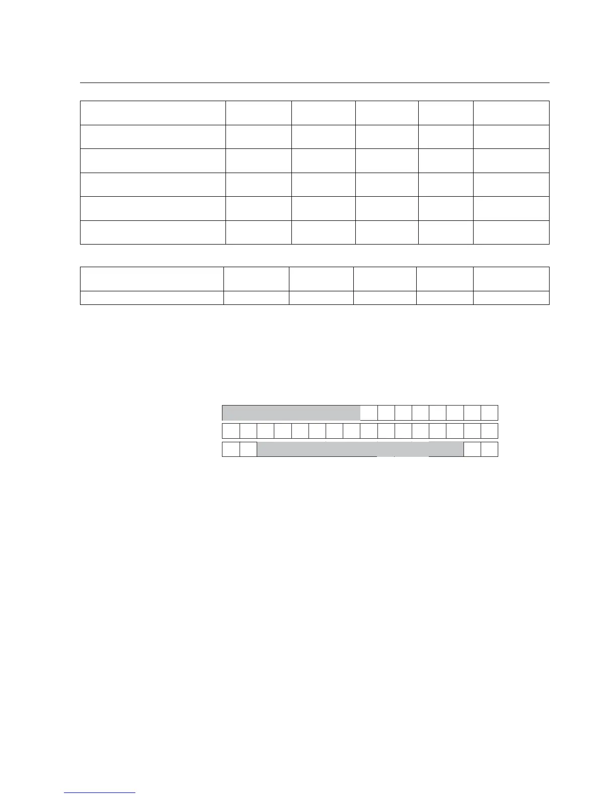
Structure 1
The status registers contain information on unread fault and event records, and relay
status. The registers are arranged as in Fig. 5.1.15.1.-2 below.
401
402
403
15 8 7 0
Reserved
Warning code
IRF code
Reserved
FR
ER
SP MP
A040333
Fig. 5.1.15.1.-2 Status registers
When the value of the FR/ER bit is 1, there is one or several unread fault/event
records. If time synchronization is realized via a digital input, either the SP (second-
pulse) or MP (minute-pulse) bit will be activated.
Refer to Table 5.1.18.-1 for IRF codes and Table 5.1.18.-2 for warning codes.
Structure 2
This structure contains data recorded during a fault sequence. Refer to Fault records
earlier in this section for the reading method.
Feeder Protection Relay
Technical Reference Manual
REF 610REF 610
1MRS755310