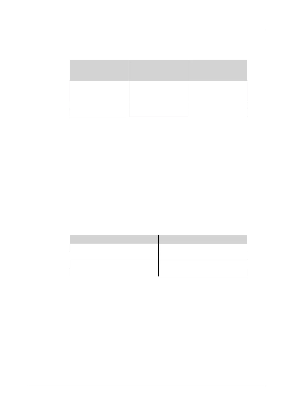
Table 49: Maximum current protection setting values
Application nominal
current (I
n
)
Rated secondary value
with 80A / 0.150 V at 50
Hz
Current protection
maximum setting value
not to be exceeded
...1250 A 1.000...46.875 mV/Hz 40 × I
n
(Also the maximum
of the start value setting
range)
1250...2500 A 46.875...93.750 mV/Hz 20 × I
n
2500...4000 A 93.750...150.000 mV/Hz 12.5 × I
n
Voltage sensor setting example
The voltage sensor is based on the resistive divider or capacitive divider
principle. Therefore, the voltage is linear throughout the whole measuring
range. The output signal is a voltage, directly proportional to the primary
voltage. For the voltage sensor all parameters are readable directly from its
rating plate and conversions are not needed.
In this example the system phase-to-phase voltage rating is 10 kV. Thus,
the
Primary voltage
parameter is set to 10 kV. For protection relays with
sensor measurement support the
Voltage input type
is always set to “CVD
sensor” and it cannot be changed. The same applies for the
VT connection
parameter
which is always set to “WYE” type. The division ratio for ABB
voltage sensors is most often 10000:1. Thus, the
Division ratio parameter
is
usually set to “10000”. The primary voltage is proportionally divided by this
division ratio.
Table 50: Example setting values for voltage sensor
Setting Value
Primary voltage 10 kV
VT connection Wye
Voltage input type 3=CVD sensor
Division ratio 10000
3.11 Binary input
3.11.1 Binary input filter time
The filter time eliminates debounces and short disturbances on a binary input. The
filter time is set for each binary input of the protection relay.
1MRS758755 C
Basic functions
REC615 & RER615
Technical Manual
91