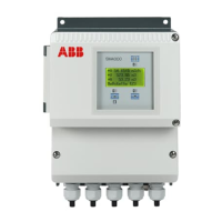
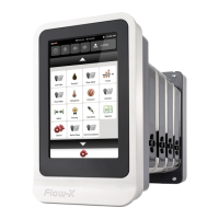
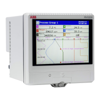
SM500F
Field mountable paperless recorder 7 Configuration
IM/SM500F Rev. Z 97
Specify the display range and units of the engineering value
corresponding to the electrical high and low values, within the limits
defined in Table 7.4:
THC/RTD Type
°C °F
Min. Max. Min. Max.
B –18 1800 0 3270
E –100 900 –140 1650
J –100 900 –140 1650
K –100 1300 –140 2350
L –100 900 –140 1650
N –200 1300 –325 2350
R & S –18 1700 0 3090
T –250 300 –400 570
Pt100 –200 600 –325 1100
Power 5/2
–999 to +9999
Power 3/2
Square Root
Custom Linearizer 1
Custom Linearizer 2
Linear
Table 7.4 Limits of Engineering Ranges
Example – for an electrical input range of 4.0 to 20.0mA, representing a
pressure range of 50 to 250 bar, set the 'Low' value to 50.0 and the 'High'
value to 250.0.
Note.
Select any of the engineering units pre-programmed into the
recorder or select 'Custom' and enter user-defined units (6
characters max.). Refer to Appendix D, Table D.1, page 163 for a
description of the pre-defined engineering units.
The recorder can be configured to calculate the totalizer count rate
automatically by ensuring that the engineering range unit of
measurement selected for the channel to which the totalizer is
assigned is a volumetric unit (i.e. quantity per unit of time, for
example gallons per hour) – see page 107. If the recorder holds the
relationship data between the selected measurement units and
totalizer units, the count rate parameter is calculated and displayed
automatically.
•1 If this parameter is changed, internally recorded data files are recreated and unarchived data is lost.
 Loading...


