12 CI/FSV/FSS/430/450-EN Rev. G | VortexMaster FSV430, FSV450 SwirlMaster FSS430, FSS450
2.4.2 Electrical and temperature data
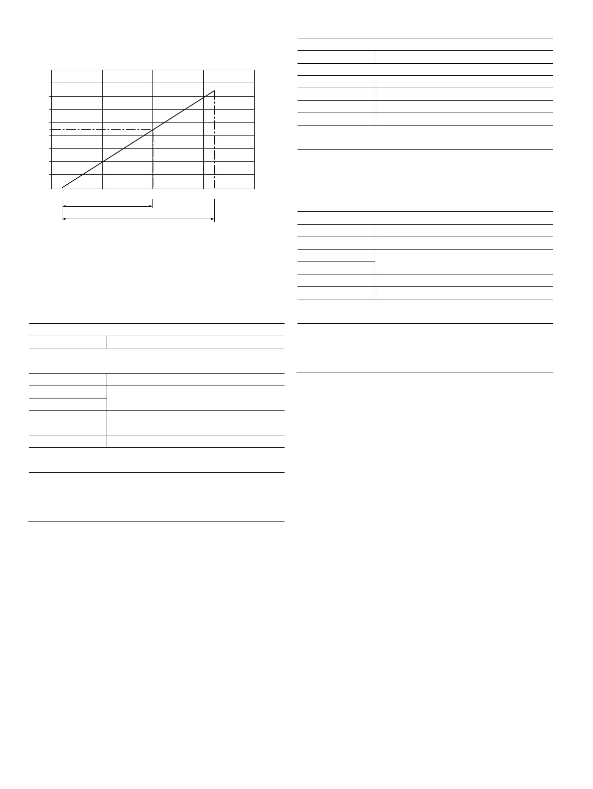
Fig. 3: Power supply in zone 0, 1, 2, explosion protection "intrinsic
safety / Intrinsically safe"
The minimum voltage U
S
of 12 V is based on a load of 0 Ω.
U
S
Supply voltage
R
B
Maximum permissible load in the power supply circuit,
e.g., indicator, recorder or power resistor.
Power supply / current output / HART output
Terminals PWR/COMM + / PWR/COMM -
Zone 0: Ex ia IIC T4 to T6 Ga
T
amb
= -40 ... 85 °C
1)
U
max
30 V
I
max
See the chapter titled "Limit value tables" on
page 13.
P
i
C
i
— 13 nF for indicator option L1
— 17 nF for all other options
L
i
10 μH
Zone 20: Ex ia IIIC T85 °C
T
amb
= -40 ... 85 °C
1)
IS/S. Intrinseque (Entity) CL I,
Zone 0 AEx/Ex ia IIC T6, T5, T4
Cl I/Div 1/ABCD IS-CL II, III/DIV 1/EFG TYPE 4X
IS Control Drawing: 3KXF065215U0109
1) See temperature ranges in the chapter titled "Limit value tables" on page 13.
Digital output
Terminals DIGITAL OUTPUT 1+ / DIGITAL OUTPUT 4-
Zone 0: Ex ia IIC T4 to T6 Ga
U
max
30 V
I
max
30 mA
C
i
7 nF
L
i
0 mH
Zone 20: Ex ia IIIC T85 °C
Tamb = -40 ... 85 °C
1)
IS/S. Intrinseque (Entity) CL I,
Zone 0 AEx/Ex ia IIC T6, T5, T4
Cl I/Div 1/ABCD IS-CL II, III/DIV 1/EFG TYPE 4X
IS Control Drawing: 3KXF065215U0109
Analog input
Terminals ANALOG INPUT + / ANALOG INPUT -
Zone 0: Ex ia IIC T4 to T6 Ga
U
max
See the chapter titled "Limit value tables" on
page 13.
I
max
C
i
7 nF
L
i
0 mH
Zone 20: Ex ia IIIC T85 °C
T
amb
= -40 ... 85 °C
1)
IS/S. Intrinseque(Entity) CL I,
Zone 0 AEx/Ex ia IIC T6, T5, T4
Cl I/Div 1/ABCD IS-CL II, III/DIV 1/EFG TYPE 4X
IS Control Drawing: 3KXF065215U0109
1) See temperature ranges in the chapter titled "Limit value tables" on page 13.
Special conditions
The devices must be installed in a protected environment in
accordance with the specific conditions on the test certificate.
Pollution degree 3 (in accordance with IEC 60664-1) should
not be exceeded for the macro environment of the device.
The devices are in accordance with IP degree of protection
IP 66 / IP 67. If the device is installed properly, this
requirement is met
by the housing as standard.
When connected to the power supply / not connected to the
power supply, the electrical circuits must not exceed
overvoltage category III / II.
For input limits or analog input limits, see the chapter titled
"Limit value tables" on page 13.
Devices with extended EMC-protection
(SIL and NAMUR design)
For the operation in the ignition protection type "Intrinsic
safety / Intrinsically safe", the current circuits on the device
must be connected over approved, electrically isolated safety
barriers.
Change from two to one column
G11784
10
0
0,2
0,4
0,6
0,8
0,9
1,0
1,2
1,4
1,6
1,8
12
Ex nA / NI
U [V]
S
R[k]
B
Ω
30 40 42 50
20
Ex /ia IS