VortexMaster FSV430, FSV450 SwirlMaster FSS430, FSS450 | CI/FSV/FSS/430/450-EN Rev. G 9
2.3.2 Electrical data
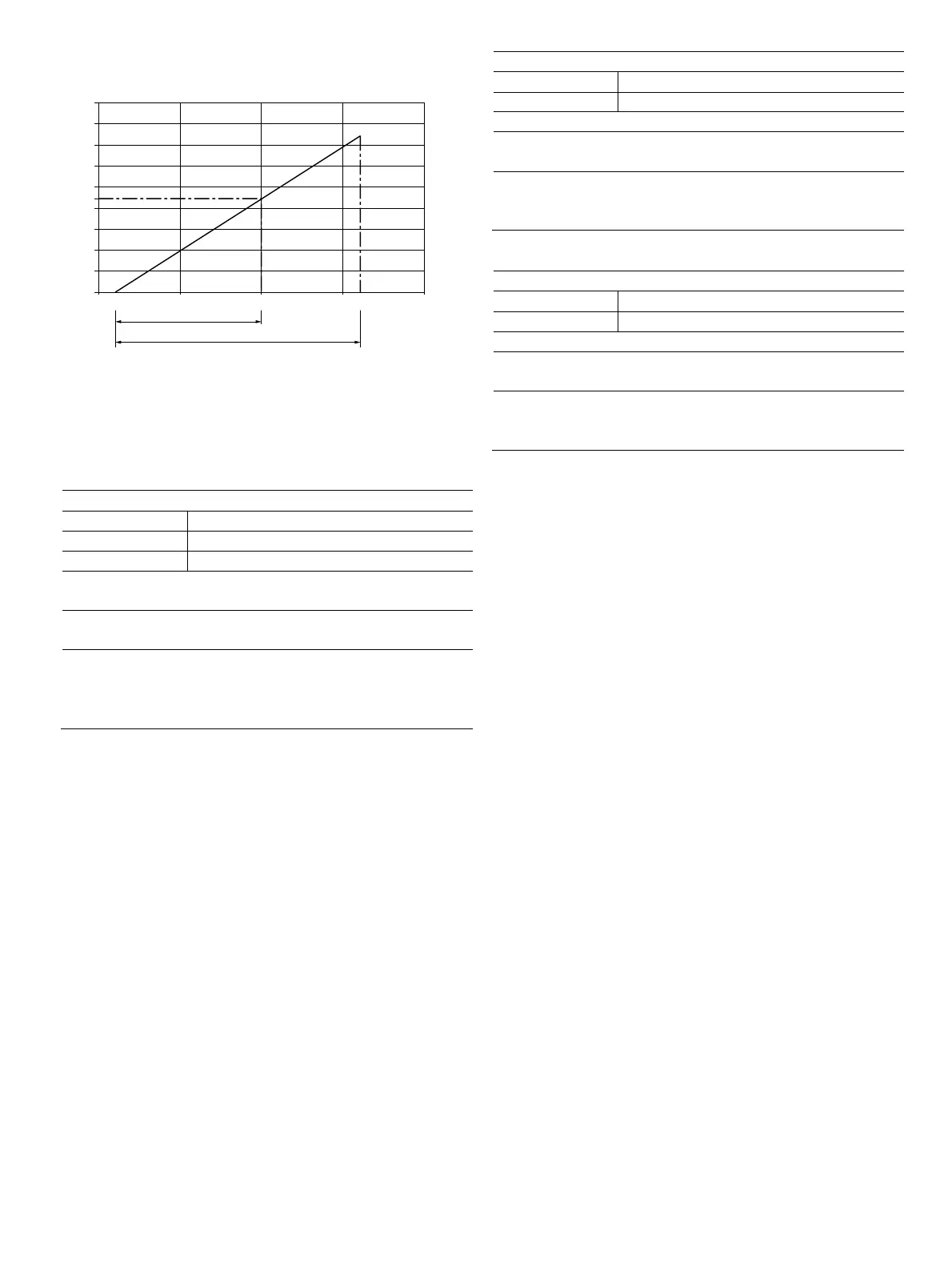
Fig. 2: Power supply in zone 2, explosion protection, non-sparking
The minimum voltage U
S
of 12 V is based on a load of 0 Ω.
U
S
Supply voltage
R
B
Maximum permissible load in the power supply circuit,
e.g., indicator, recorder or power resistor.
Power supply / current output / HART output / Modbus
HART terminals PWR/COMM + / PWR/COMM -
Modbus terminals A (+), B (-) / PWR +, PWR -
U
S
HART: 45 V, Modbus: 30 V
Zone 2: Ex nA IIC T4 to T6 Gc
T
amb
= -40 ... xx °C
1)
Zone 22: Ex tc IIIC T85 °C Dc
T
amb
= -40 ... 75 °C
CL I, ZONE 2 AEx/Ex nA IIC T6, T5, T4
CL I/DIV 2/GP ABCD TYPE 4X
NI CL 1/DIV 2/GP ABCD, DIP CL II,III/DIV 2/GP EFG
Housing: TYPE 4X
1) The temperature xx °C depends on the temperature class T
class
Digital output
Terminals DIGITAL OUTPUT 1+ / DIGITAL OUTPUT 4-
U
M
45 V
Zone 2: Ex nA IIC T4 to T6 Gc
Zone 22: Ex tc IIIC T85 °C Dc
T
amb
= -40 ... 75 °C
1)
CL I, ZONE 2 AEx/Ex nA IIC T6, T5, T4
CL I/DIV 2/GP ABCD TYPE 4X
NI CL 1/DIV 2/GP ABCD, DIP CL II,III/DIV 2/GP EFG
1) See temperature ranges in the chapter titled "Temperature data" on page 10.
Analog input
Terminals ANALOG INPUT + / ANALOG INPUT -
U
M
45 V
Zone 2: Ex nA IIC T4 to T6 Gc
Zone 22: Ex tc IIIC T85 °C Dc
T
amb
= -40 ... 75 °C
CL I, ZONE 2 AEx/Ex nA IIC T6, T5, T4
CL I/DIV 2/GP ABCD TYPE 4X
NI CL 1/DIV 2/GP ABCD, DIP CL II,III/DIV 2/GP EFG
Special conditions
The devices must be installed in a protected environment in
accordance with the specific conditions on the test certificate.
Pollution degree 3 (in accordance with IEC 60664-1) should
not be exceeded for the macro environment of the device.
The devices are in accordance with IP degree of protection IP
66 / IP 67. If the device is installed properly, this requirement
is met by the housing as standard.
When connected to the power supply / not connected to the
power supply, the electrical circuits must not exceed
overvoltage category III / II.
Overvoltage protection
For the devices, the client must provide an external
overvoltage protection.
It must be ensured that the overvoltage is limited to 140 %
(HART: 63 V DC or Modbus: 42 V DC) of the maximum
operating voltage U
S
.
G11784-01
10
0
0,2
0,4
0,6
0,8
0,9
1,0
1,2
1,4
1,6
1,8
12
Ex nA / NI (HART)
U [V]
S
R[k]
B
Ω
30 40 42 50
20
Ex A /n NI (Modbus)