VortexMaster FSV430, FSV450 SwirlMaster FSS430, FSS450 | CI/FSV/FSS/430/450-EN Rev. G 21
Fig. 8: Pipe sections with pipe elbows
Installation Inlet section Outlet section
Single pipe elbow
upstream or
downstream of the
meter tube
min. 3 x DN min. 1 x DN
If the elbow radius of single or double pipe elbows positioned
upstream or downstream of the device is greater than
1.8 x DN, inlet and outlet sections are not required.
VortexMaster FSV430, FSV450
In order to maximize operational reliability, the flow profile at
the inflow end must not be distorted if at all possible.
The figures below show the recommended inlet and outlet
sections for various installations.
Fig. 9: Straight pipe sections
Installation Inlet section Outlet section
Straight pipe min. 15 x DN min. 5 x DN
B Valve upstream of
the meter tube
min. 50 x DN min. 5 x DN
Pipe reduction min. 15 x DN min. 5 x DN
Pipe extension min. 18 x DN min. 5 x DN
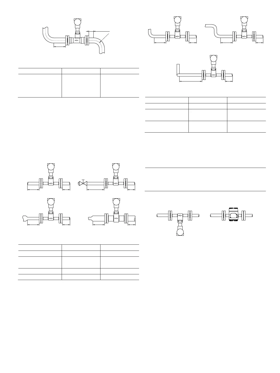
Fig. 10: Pipe sections with pipe elbows
Installation Inlet section Outlet section
Single pipe elbow min. 20 x DN min. 5 x DN
B S-shaped pipe
elbow
min. 25 x DN min. 5 x DN
C Three-dimensional
pipe elbow
min. 40 x DN min. 5 x DN
5.1.3 Avoiding cavitation
To avoid cavitation, a static overpressure is required
downstream of the flowmeter (downstream pressure). This can
be estimated using the following formula:
ppp
6,23,1
21
ρ
1
ρ
2
ρ'
Static gauge pressure downstream of the device (mbar)
Steam pressure of fluid at operating temperature (mbar)
Pressure drop, measuring medium (mbar)
5.1.4 Installation at high measuring medium temperatures
Fig. 11: Installation at high measuring medium temperatures
At high measuring medium temperatures > 150 °C (> 302 °F),
the sensor must be installed so that the transmitter is pointing
to the side or downward.
G11752
≥3 x DN
≥1 x DN
≥1,8 x DN
G11751
≥15 x DN ≥ 5 x DN ≥50 x DN ≥ 5 x DN
≥15 x DN ≥ 5 x DN ≥18 x DN ≥ 5 x DN
A
B
CD
G11752
≥ 20 x DN ≥ 5 x DN
A
B
≥ 25 x DN ≥ 5 x DN
C
≥ 40 x DN ≥ 5 x DN
G11755