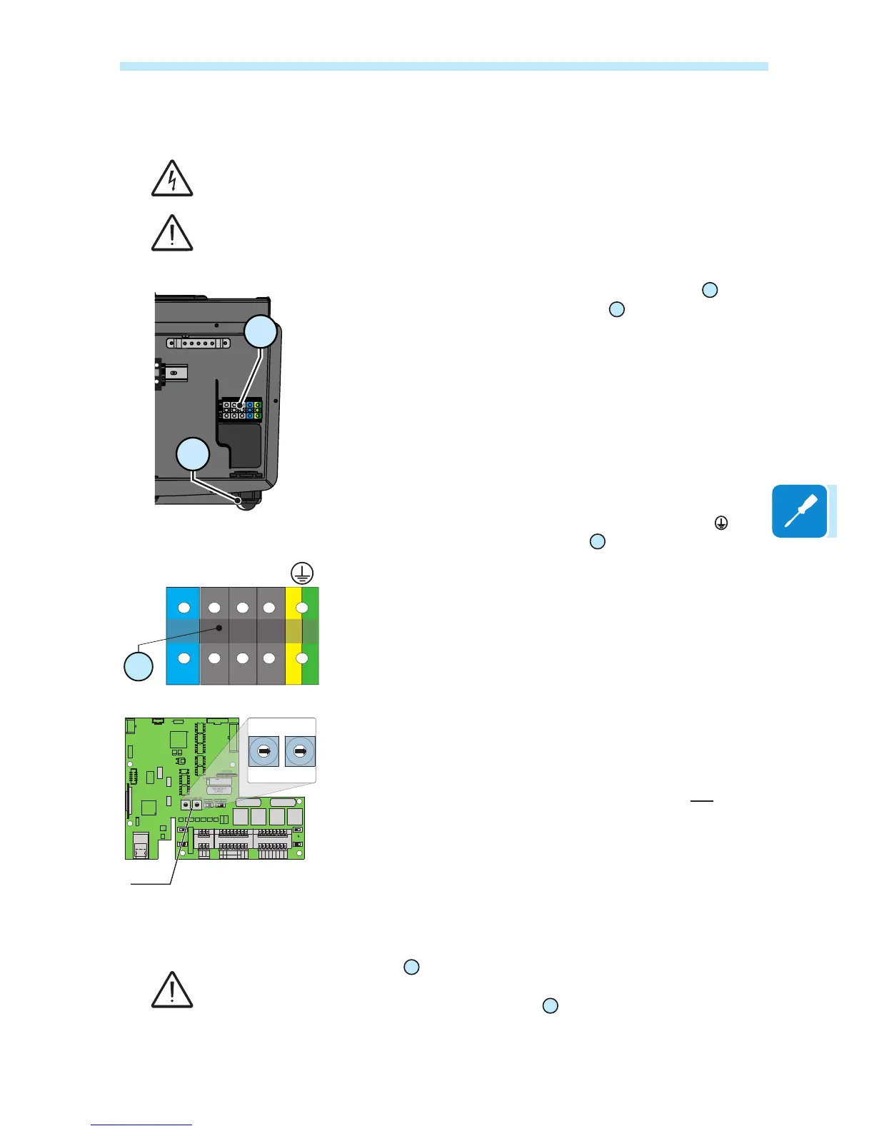
Connection to the AC side terminal board
To prevent electrocution hazards, all the connection operations must be carried out with the
disconnect switch downstream of the inverter (grid side) open and locked.
Be careful not to change round one of the phases with neutral!
High leakage current. Grounding is essential before connection to the power supply network.
For all models, connection with the AC output terminal board
17
is made
by inserting the cables in the AC cable gland
16
.
The maximum accepted cable cross-section ranges from 20 to 32 mm,
whereas each individual terminal of the terminal board accepts a cable
with cross-section of up to 35 mm
2
.
AC cable installation:
• Unscrew the cable gland and remove the cover
• Enter the appropriate section cable through the AC cable gland
• Connect the conductors Neutral, R, S, T and Protective Earth ( ) to the
terminals on the AC output terminal block
17
.
The connection of the inverter to the grid can be with three wires (delta
conguration) or with four wires (star conguration).
Before connecting the inverter to the national grid, the standard of the
country must be set. To do this, turn the two rotary switches a05 following
the table shown in the relevant chapter.
• Once the connection to the terminal board is complete, screw in the
cable gland rmly and check the tightness.
The AC output terminal block
17
accepts connection of copper cables. If aluminium cables
are used, bimetallic cable terminals of a suitable type must be used to connect the aluminium
cables to the contacts in the AC output terminal block
17
.
17
16
CARD
J10
PC
OFF
TERM.
120
OFF
J8
ON
PMU
S2
S4
ON
PC
PMU
J9
PMU -T/R
J6
CARD
COM
PMU +T/R
GND COM
+5V OUT
R ON/OFF
J4
PC
SH
J7
PC +T/R
PC -T/R
GND
RTD3
RTD3
24V
-WTACH
J5
+WTACH
PT100
RTD2
RTD2
PT1000
J3
J2
PMU
CR2032
A2
COM
A2
RTD1
RTD1
A1
A1
COM
S6
NORM
S3
S7
COUNTRY/LANG SEL
K1
S8
MEMORY
ALARM
NC
C
BT1
NO
S5
PAR IND SERV
A1
J16
J14
J11
AN2 AN1
V
mA
V
mA
S1

 Loading...