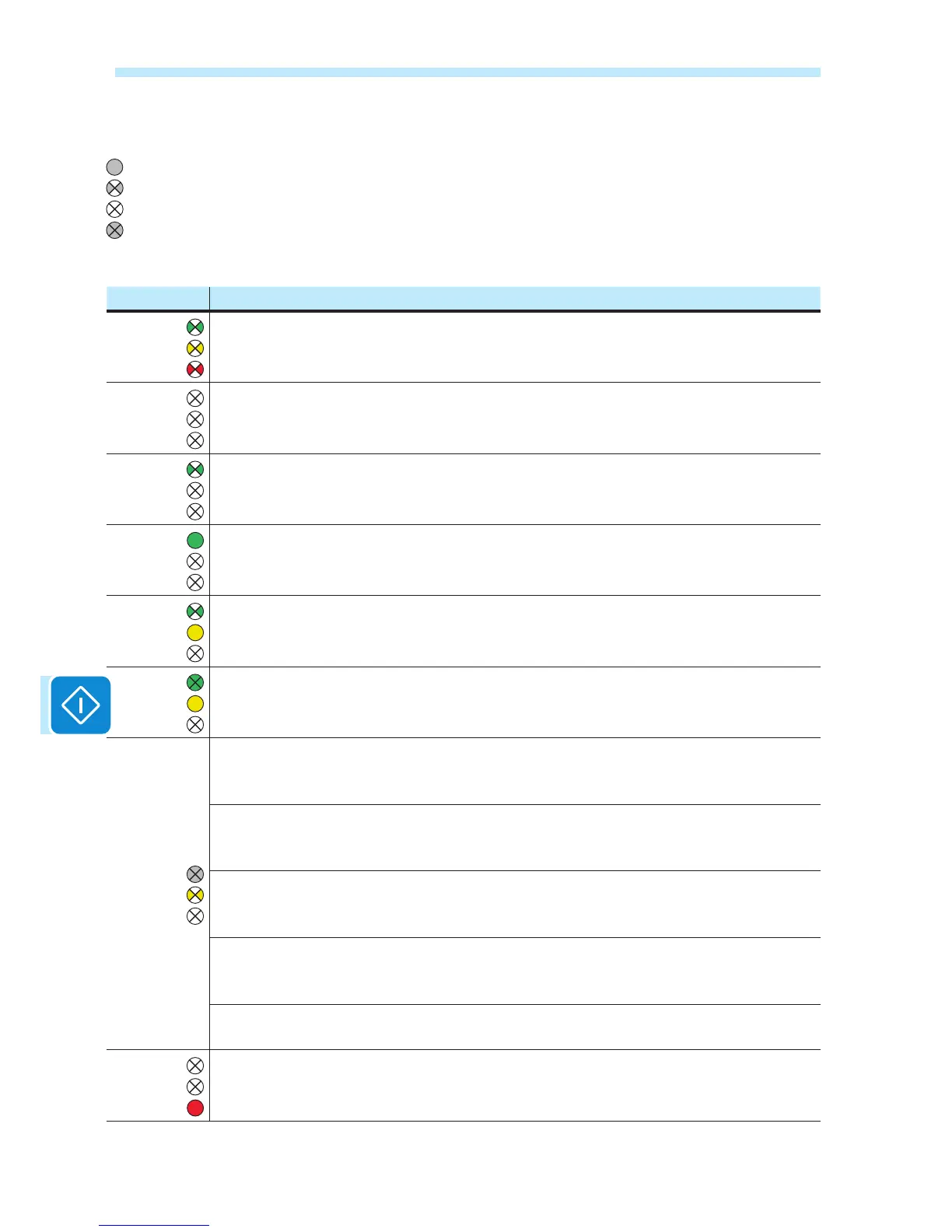
LED behaviour
The following table shows all the possible activation combinations of LEDs
on the LED panel according to the operating status of the inverter.
LED status Operating state
green:
yellow:
red:
Firmware programming
The inverter rmware is being programmed
green:
yellow:
red:
Night mode (inverter automatically switches off)
The inverter is in night time switch-off mode (input voltage less than 70% of the set start-up
voltage).
green:
yellow:
red:
Inverter initialisation
This is a transitional state during verication of the operating conditions. During this stage the
inverter checks that the conditions for connecting to the grid are met.
green:
yellow:
red:
The inverter is connected and is feeding power into the grid
Normal operation During this stage, the inverter automatically tracks and analyses the photo-
voltaic generator's maximum power point (MPP).
green:
yellow:
red:
Disconnection from the grid
Indicates no grid voltage. This condition does not allow the inverter to connect to the grid (the
inverter display shows the message "Missing Grid").
green:
yellow:
red:
Indication of Warning (W message codes) or Error (E message codes) states
Indicates that the inverter control system has detected a warning (W) or error (E). The display
shows a message indicating the type of problem found (see Alarm messages).
green:
yellow:
red:
• Ventilation anomaly
Indicates an anomaly in the operation of the internal ventilation system that could limit output
power at high ambient temperatures.
• Failed association of internal inverter components (after replacement)
Indicates that the installed wiring box (only in the event of a replacement) was already associ-
ated with another inverter and cannot be associated with the new inverter
• Overvoltage surge arresters triggered (where tted)
Indicates that any class II overvoltage surge arresters installed on the AC or DC side have
been triggered
• String protection fuses triggered (where tted)
Indicates that one or more input string protection fuses that may be installed have been trig-
gered
• Autotest (for Italian grid standards only)
The inverter is performing a self-test
green:
yellow:
red:
Anomaly in the insulation system of the photovoltaic generator
Indicates that a leakage to ground from the FV generator has been detected, causing the
inverter to disconnect from the grid.
= LED On
= LED ashing
= LED Off
= Any one of the conditions
described above

 Loading...