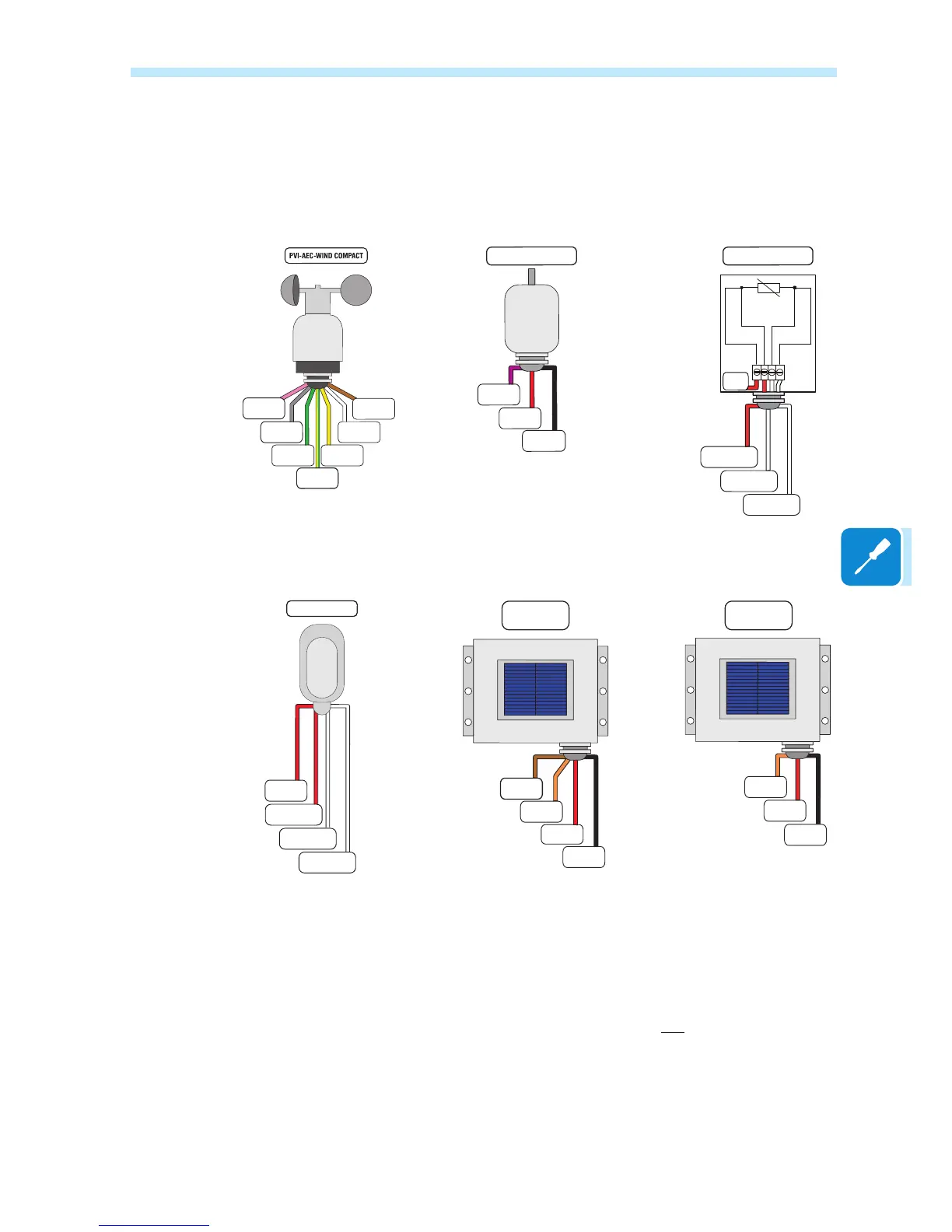
Connection diagrams for environmental sensors
Connection diagrams for the main sensors marketed by ABB are shown
below: For non-conventional installations or additional information about
the connections, please contact the technical support department.
A1/A2
(Wind speed)
A1/A2_RTN
+Vcc
-Vcc
Ground
+Vcc_Heat
(external)
-Vcc_Heat
(external)
R
G
E
T
N
I
-
0
0
0
1
T
-
C
E
A
-
I
V
P
+Vcc
A1/A2_RTN
-Vcc
A1/A2
H
D
A
-
0
0
1
T
-
C
E
A
-
I
V
P
N.C.
RTD1PT100
(PT_RTN)
(PT_SENSE)
(PT_ALIM)
RTD2PT100
RTD3PT100
)
e
c
n
a
i
d
a
r
r
I
(
)
e
r
u
t
a
r
e
p
m
e
t
(
PVI-AEC-RAD-13-TC-T
PVI-AEC-IRR-T
A1
A2
+Vcc
A1/A2_RTN
-Vcc
PVI-AEC-RAD-13TC
A1/A2
A1/A2_RTN
+Vcc
-Vcc
PVI-AEC-IRR
RTD1PT1000
(PT_RTN)
(PT_SENSE)
(PT_ALIM)
RTD2PT1000
RTD3PT1000
PVI-AEC-T1000-BOX
N.C.
5 V auxiliary output connection
There is an auxiliary 5 V output on connector a11. The maximum allowed
absorption by this auxiliary supply voltage is 100 mA.

 Loading...