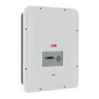
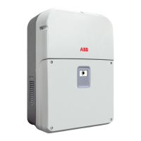
Do you have a question about the ABB TRIO-50.0-TL-OUTD and is the answer not in the manual?
Conditions for warranty validity and adherence to manual instructions.
Information on items not part of the standard supply package.
Defines the intended readers and the manual's purpose.
Required qualifications and skills for personnel operating and maintaining the inverter.
Explanation of symbols and signs used in the manual and on the equipment.
Defines the intended use and general conditions for operating the inverter.
General information on equipment characteristics and technical terminology.
Details on identifying the inverter's manufacturer and specific equipment models.
Overview of different DC wiring box, AC wiring box, power module, and bracket models.
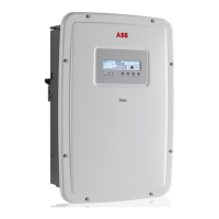
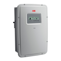
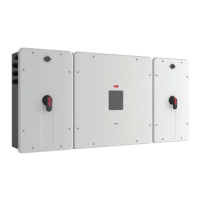
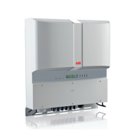
Visual identification and list of key components of the inverter system.
Detailed breakdown and identification of different DC wiring box versions.
Detailed breakdown and identification of different AC wiring box versions.
Description of key components within the wiring boxes, including disconnect switches and surge arresters.
Comprehensive technical specifications, input/output parameters, and protection features of the inverter.
Specified torque values for screws and cable glands to ensure IP65 protection and proper installation.
Dimensions for cable gland clamping to ensure secure cable connections.
Visual representation and dimensions of the inverter, including mounting brackets.
Detailed dimensions for the vertical wall mounting bracket.
Detailed dimensions for the horizontal wall mounting bracket.
Graphs illustrating the inverter's efficiency at different output power levels and voltages.
Explains automatic power reduction due to thermal or grid conditions.
Details on how ambient temperature affects inverter output power.
Graph showing power reduction based on DC input voltage levels.
Graph showing power reduction based on AC grid voltage levels.
Illustrates the inverter's capability to adjust active and reactive power output.
Basic principles of PV generators, strings, and arrays.
Explanation of how PV modules are connected in series (strings) and parallel (arrays).
Overview of the string inverter's function and operation.
Diagram illustrating the functional connections of the inverter system.
How to connect multiple inverters for larger PV systems.
Factors to consider when sizing a PV system and available sizing tools.
Details on configurable relays, remote control, reactive power, power limiting, and monitoring functions.
Summary of the inverter's internal structure and conversion stages.
General safety guidelines and instructions for installation and operation.
Information on environmental risks and hazardous operations related to the equipment.
Importance of not removing, damaging, or hiding equipment labels and symbols.
Warnings about hot surfaces and electrical hazards during operation and maintenance.
Recommendations for personal protective equipment (PPE) and appropriate clothing.
Identification of residual risks that cannot be eliminated and suggested remedies.
General recommendations for transport and handling of the equipment.
Guidelines for safe transport and handling to prevent damage from shocks and movements.
Procedures and precautions for safely lifting the inverter components using suitable equipment.
Instructions for safely unpacking and checking the equipment for damage or missing parts.
Proper storage conditions and stacking limits for power modules and wiring boxes.
Table detailing the weight, lifting points, and dimensions of the inverter modules.
Methods for lifting the power module and wiring boxes, including the use of handles and eyebolts.
Inventory of components included with the inverter for installation.
List of available spare parts kits for maintenance and repair.
General considerations for installation, emphasizing qualified personnel and correct connections.
Guidelines for selecting an appropriate installation site and position for the inverter.
Specific considerations and prohibitions for installations at altitudes exceeding 2000 meters.
Precautions and warnings regarding installations in high humidity environments.
Detailed instructions for mounting the inverter using vertical and horizontal support brackets.
Step-by-step guide for mounting the inverter on a vertical wall.
Step-by-step guide for mounting the inverter on a horizontal surface.
Instructions for connecting the inverter to the AC grid, including grounding requirements.
Requirements for selecting and installing the protective grounding cable.
Guidelines for selecting the AC line cable cross-section and maximum length.
Specifications for the required AC overcurrent protection device.
Procedures for connecting AC cables to the terminal blocks for standard and -S/-SX models.
Detailed steps for installing AC cables, including earth connection and terminal connections.
Procedure for installing an additional protective earthing cable if required by local regulations.
Preliminary checks and grounding procedures before connecting the PV generator.
Method for checking PV generator leakage to ground before connection.
Procedure for checking the voltage of PV strings and system sizing.
Ensuring correct polarity of PV strings for standard and -S versions.
Information on integrated ground fault protection and required AC protection devices.
How to configure the inverter's input channels for PV generator connection.
Guidelines for connecting the PV generator to the inverter's DC input.
Connecting PV strings to standard and -S model DC input terminal boards.
Connecting PV strings using quick-fit connectors on -SX/-SY models.
Procedure for checking PV string polarity in -SX/-SY versions.
Detailed steps for installing different types of quick-fit connectors.
Information on string protection fuses for -SX/-SY models and their sizing.
Guidelines for correctly sizing string protection fuses based on PV string parameters.
Identification and description of components on the communication and control board.
How to connect cables to the communication and control board via cable glands.
Setting up remote control for connecting/disconnecting the inverter from the grid.
Connecting external devices to the inverter's configurable relays.
Installing optional expansion boards using the dedicated connector.
Installing optional PMU expansion boards.
Procedures for establishing RS485 serial communication for monitoring and control.
Setting up communication lines for monitoring and control systems.
Step-by-step guide for connecting the inverter chain to a monitoring system via RS485.
General advice on understanding and using the inverter's instruments for safe operation.
Explanation of the status and error indications provided by the inverter's LEDs.
Specific intervention steps for insulation fault warnings indicated by the red LED.
Overview of the Aurora Manager LITE software for monitoring and configuration.
Prerequisite knowledge and conditions for operating the inverter safely and effectively.
How the inverter operates automatically and transmits data via RS485.
Methods used by the inverter to provide operational information, including LEDs and data transmission.
Distinction between real-time and internally stored data accessible through the software.
General tolerances for measurements provided by the inverter compared to certified instruments.
Essential preliminary steps required before the inverter can be commissioned.
Procedure for setting the correct national grid standard using rotary switches.
How inverter settings are frozen after operation and how to check grid standards.
Steps for correctly fitting wiring box covers and conductive springs for IP rating.
Step-by-step procedure for commissioning the inverter.
Checklist of essential checks before initiating the commissioning procedure.
Detailed sequence of operations for commissioning the inverter and observing LED indicators.
Overview of main parameters that can be modified using Aurora Manager Lite software.
Detailed explanation of various LED status combinations and their meanings.
Description of parameters that can be changed via Aurora Manager Lite and their ranges.
How to manage reactive power supply to the grid using different management modes.
Configuring reactive power output based on grid voltage using Aurora Manager Lite.
Setting the time the inverter stays connected to the grid after voltage drops.
Configuring MPPT scan for optimizing power tracking, especially in shaded conditions.
Adjusting the limit for active power fed into the grid based on nominal power.
Accessing product ID, serial number, firmware, and grid standard information via software.
Safe procedure for turning off the inverter and its components before maintenance.
Specific switch-off procedure for standard AC/DC wiring box versions.
Switch-off procedures for different DC and AC wiring box versions.
Guidelines for performing maintenance operations by specialized personnel, emphasizing safety.
Recommended periodic maintenance tasks to ensure optimal PV system efficiency.
Checks for proper operation, visible labels, cable integrity, and environmental conditions.
Tasks like checking cable glands, front cover security, and operating disconnect switches.
Cleaning the equipment, focusing on cooling fan assembly and heat sink.
How the inverter signals errors and warnings via LEDs and software.
Step-by-step instructions for replacing DC string fuses in -SX/-SY models.
Procedure for replacing the CR2032 buffer battery on the communication and control board.
Method for measuring PV generator leakage to ground.
How leakage is detected and indicated by voltage stabilization at 0V.
How leakage is indicated by voltage stabilization at a non-zero value, with example.
Procedure for measuring PV generator insulation resistance using a megohmmeter.
Guidelines for storing the equipment and procedures for dismantling and disposal.
Instructions for storing equipment not in immediate use and checks after prolonged stops.
Responsibilities and methods for proper dismantling, decommissioning, and waste disposal.
| Model | TRIO-50.0-TL-OUTD |
|---|---|
| Type | String Inverter |
| Maximum Output Power | 50 kW |
| Input Voltage Range | 200 - 1000 V |
| Number of MPPT | 2 |
| Protection Class | IP65 |
| Max. DC Voltage | 1000 V |
| AC Voltage | 400 V |

