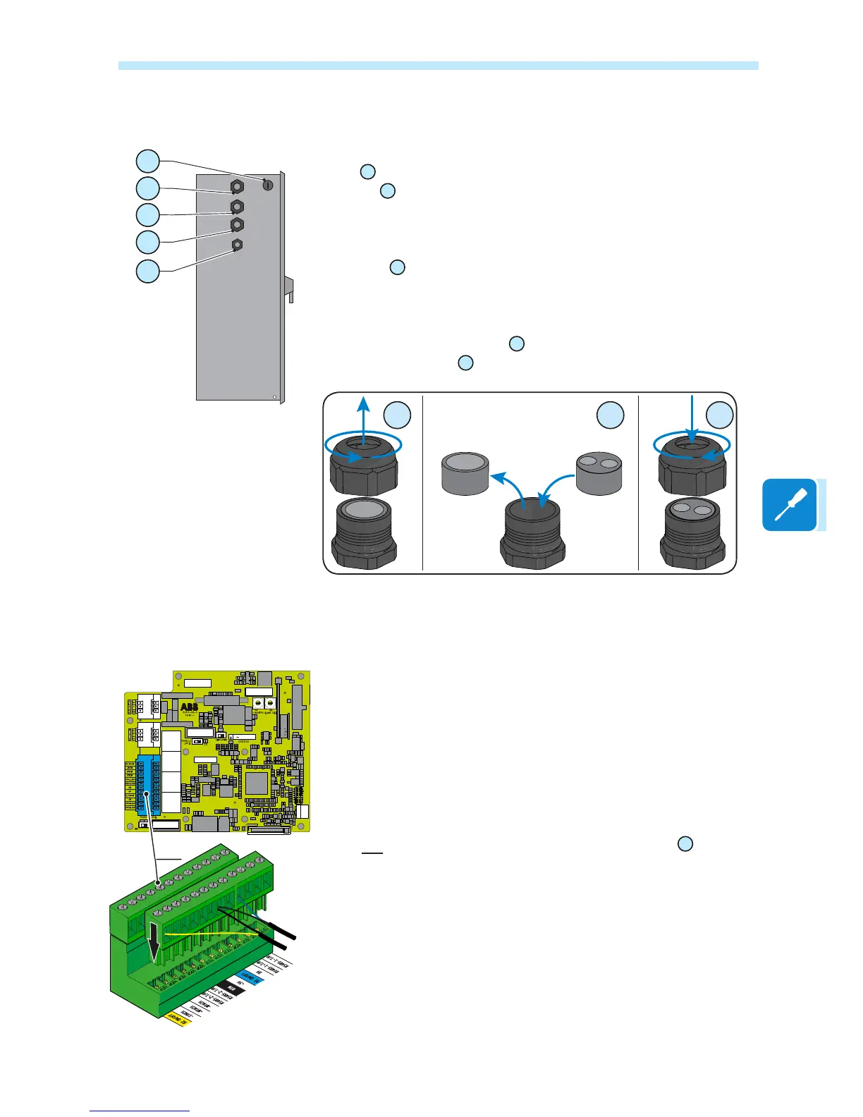
Connections to the communication and control board
Each cable which must be connected to the communication and control
board
09
must pass through the following cable glands:
• An M25
34
PG21 that takes cables from 10 mm to 17 mm in diameter.
Gaskets with two holes are supplied as standard to insert into the cable
gland, which allow two separate cables of a maximum cross-section of 6
mm to be accommodated
• Two M20
35
PG16 that take cables from 7 mm to 13 mm in diameter.
Gaskets with two holes are supplied as standard to insert into the cable
gland, which allow two separate cables of a maximum cross-section of 5
mm to be accommodated
• The PG 21 service cable gland
34
is intended for the RS485 connection.
• The M20 cable gland
33
is intended for the Wi-Fi aerial connection.
Remote control connection
The connection and disconnection of the inverter to and from the grid can
be controlled through an external control.
The function must be enabled in the relevant menu through the Aurora
Manager Tools software. If the remote control function is disabled, the
switching on of the inverter is dictated by the presence of the normal
parameters which allow the inverter to connect to the grid.
If the remote control function is operating, besides being dictated by the
presence of the normal parameters that allow the inverter to connect to the
grid, the switching on of the inverter also depends on the state of the R1
ON/OFF and R2 ON/OFF terminals compared to the RTN terminal present
on the a11 connector of the communication and control board
09
.
When one of the R1 ON/OFF or R2 ON/OFF signals is brought to the
same potential as the RTN signal (i.e. by making a short circuit between
the two terminals of the connector), this causes the inverter to disconnect
from the grid.
The connections of these controls are made between the “R1 ON/OFF”
and the "R1 ON/OFF" inputs compared to the common "RTN" signal.
Since this is a digital input, there are no requirements to be observed
as regards cable cross-section (it only needs to comply with the sizing
requirement for passing cables through the cable glands and the terminal
connector).
35
33
34
34
34
ON
3
2
1
OFF
S6
ON
3
2
1
OFF
S6
R46
R49
3
2
1
J1
J18
J7 J5
J8
X5
2
2
1
2
1
18
17
1
18
17
J6
J15
J22
J9
J10 J11 J12
J16
0
1
2
3
4
5
6
7
8
9
A
B
C
D
E
F
0
1
2
3
4
5
6
7
8
9
A
B
C
D
E
F
a11
R2 ON/OFF
R1 ON/OFF

 Loading...