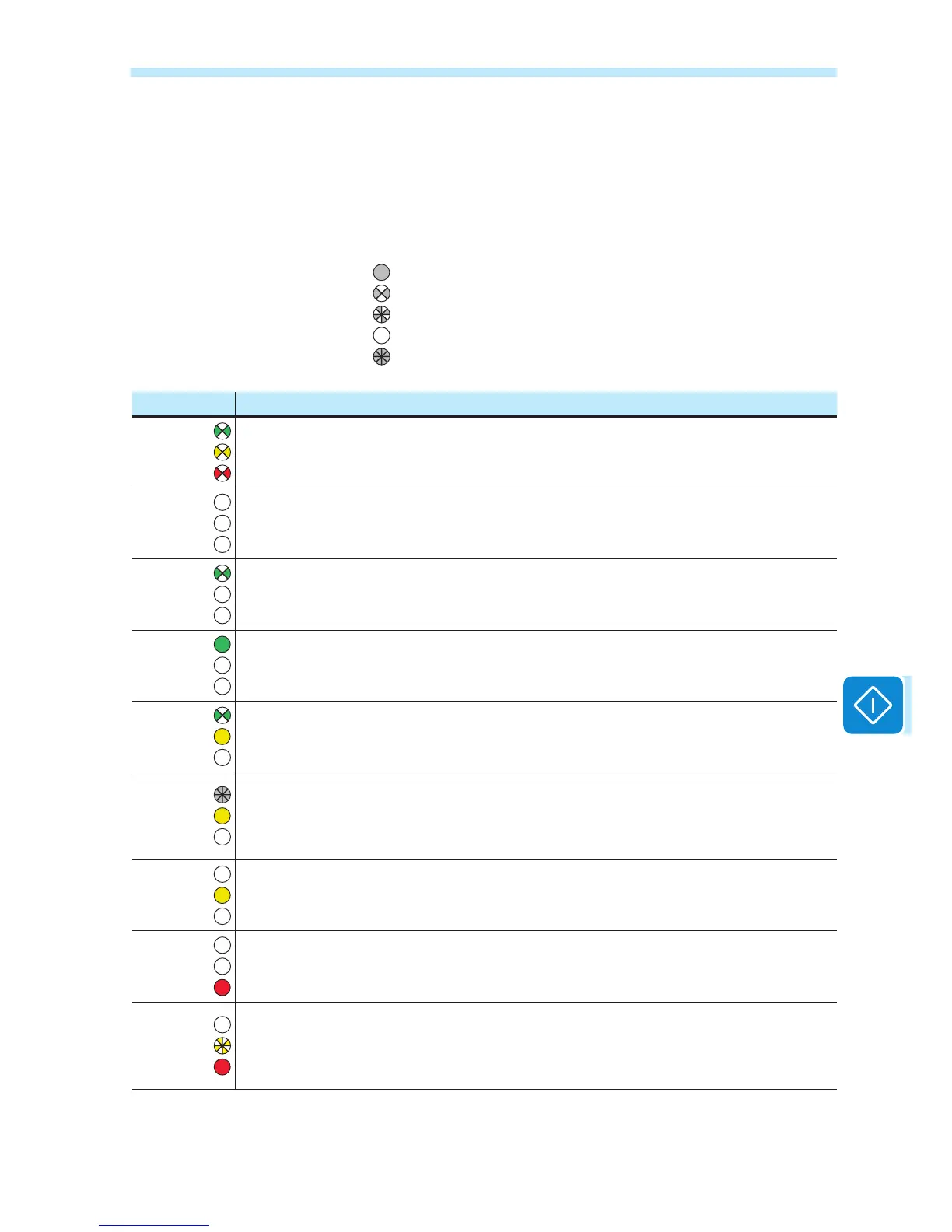
LED behaviour
The LEDs on the front panel may behave in different ways depending on
the inverter’s operational status.
All possible LED activation combinations are shown in the following ta-
ble. In particular, each LED could behave in one of the following ways:
= LED on
= LED ashing slow (2 seconds on / 2 seconds off)
= LED ashing fast (0.2 seconds on / 0.2 seconds off)
= LED off
= Any one of the conditions described above
LED status Operating state
green:
yellow:
red:
Firmware programming
The inverter rmware is being programmed
green:
yellow:
red:
Night mode (inverter automatically switches off)
The inverter is in night time switch-off mode (input voltage less than 70% of the set start-up
voltage).
green:
yellow:
red:
Inverter initialization
This is a transitional state due to verication of the operating conditions. During this stage the
inverter checks that the conditions for connecting to the grid are met.
green:
yellow:
red:
The inverter is connected and is feeding power into the grid
Normal operation. During this stage, the inverter automatically tracks and analyses the pho-
tovoltaic generator's maximum power point (MPP).
green:
yellow:
red:
Disconnection from the grid
Indicates lack of grid voltage. This condition does not allow the inverter to connect to the grid
(the inverter display shows the message "Missing Grid").
green:
yellow:
red:
Warning indication: (W message codes) or Error: (E message codes)
- Indicates that the inverter control system has detected a warning (W) or error (E). It is possible
to identify the type of problem generated with the Aurora Manager LITE software (see the alarm
messages).
green:
yellow:
red:
Temperature protection trip
Indicates that the trip relating to internal temperatures (insufcient or excessive temperature)
may have been activated
green:
yellow:
red:
Anomaly in the insulation system of the photovoltaic generator
Indicates that a leakage to earth from the PV generator has been detected, causing the in-
verter to disconnect from the grid.
green:
yellow:
red:
• Front cover open
The sensors located inside the wiring box are warning that one or both of the front co-
vers is missing or not correctly installed. This condition prevents the commissioning of the
equipment.

 Loading...