Grid output connection (AC side)
The inverter must be connected to a three-phase system with the center
of the star connected to ground. To connect the inverter to the grid is
possible to choose between the four-wire connection (3 phases + neutral)
and the three-wire connection (3 phases).
In any case, the inverter’s earth connection is mandatory.
The cable to be used can be ve-pole (four-wire conguration), or four-
pole (three-wire conguration).
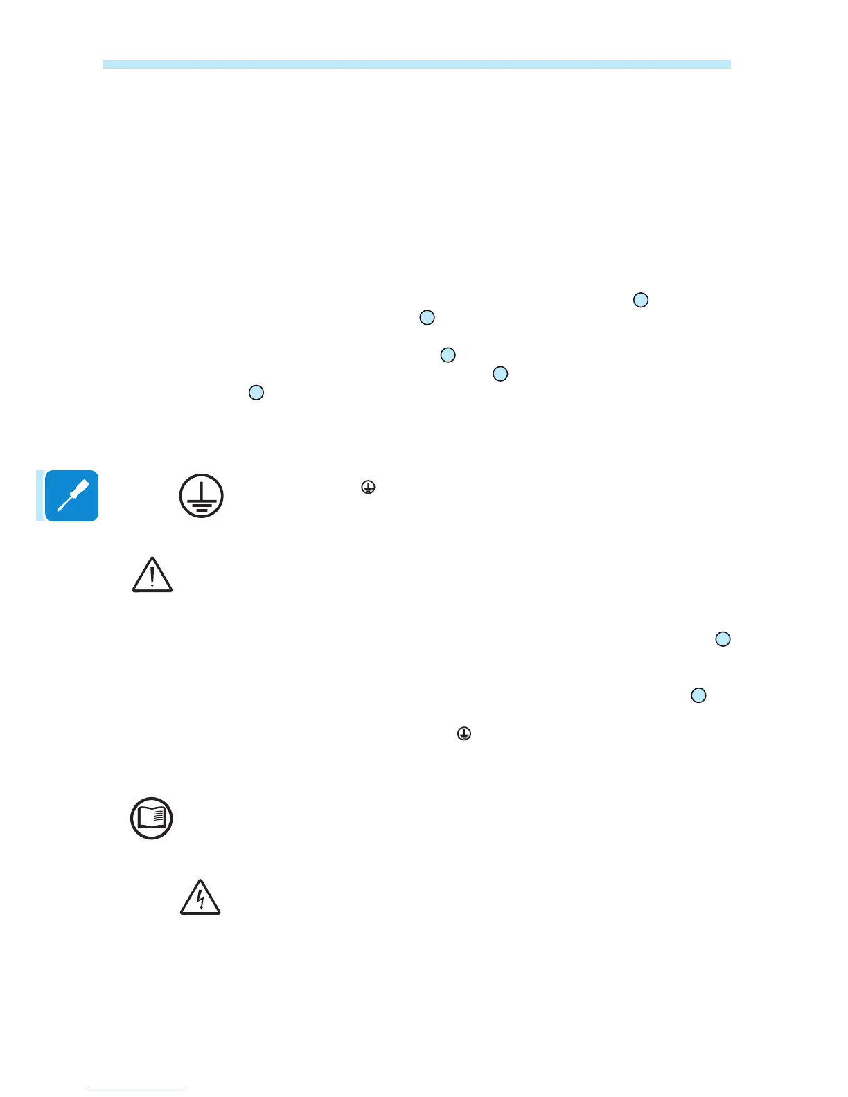
The connections can also be made with the AC wiring box
05
detached from
the power module
03
which can be connected later for commissioning.
When working with the AC wiring box
05
detached, pay particular attention to outdoor
installations, where the interface quick connectors
23
must always be protected by installing
the cap
04
on the housing.
Characteristics and sizing of the protective grounding cable
ABB inverters must be earthed via the terminal with the protective earth
symbol and using a cable with an appropriate conductor cross-section
for the maximum ground fault current that the generating system might
experience.
Any failure of the inverter when it is not connected to earth through the appropriate terminal
is not covered by the warranty.
In compliance with standard IEC 62109 it is necessary:
• Install a copper grounding cable on the ground protection terminal
20
with a minimum section of 25 mm
2
.
• It is possible to install a second grounding cable (with the same
section as the one installed on the ground protection terminal
20
) on
the connection point located on the underside of the power module and
marked with the symbol .
Installation of a second protective earthing cable is also required by
regulations in force in certain countries of installation.
If necessary, carefully read the instructions provided in the paragraph "Installation of the
second protective earthing cable".
Before connecting the inverter to a hazardous source of AC or DC
voltage, once the earth connections between the inverter modules have
been made (and in the same way that the temporary earth connections
during the assembly or dismantling stage of the system were made), use
a suitable multimeter to test the conductivity of the earth connections
between:
- a screw on the cover of the AC wiring box and a screw on the cover of
the DC wiring box
- a screw on the cover of the AC wiring box and a screw on the cover of
the power module

 Loading...