Display and keyboard
Display fields and symbols description
Using the display, operating parameters for the equipment are shown.
signals, alarms, channels, voltages, etc.
The display, when in operation, behaves dynamically, allowing cyclical
display of certain information (see relevant chapter).
DC
AC
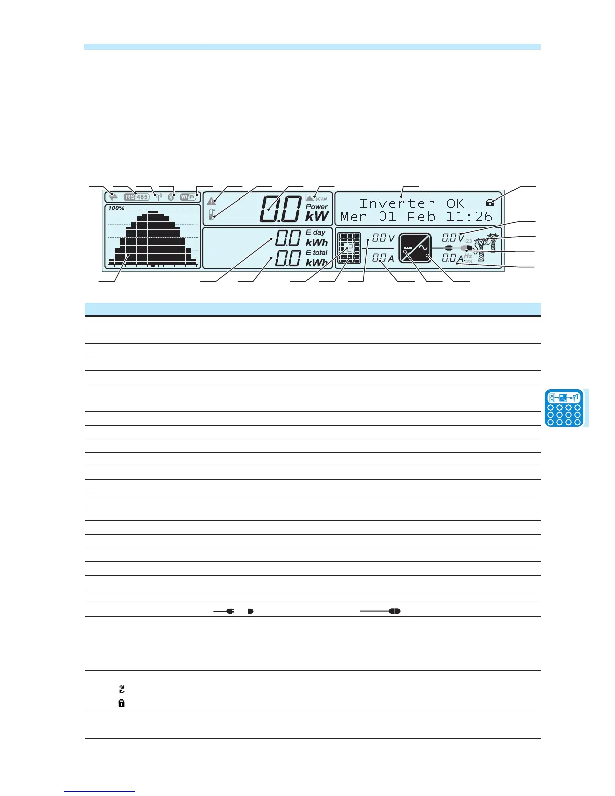
b02 b03 b04 b05 b06 b08 b09b07b01
b11 b12b13 b24 b14 b15 b16 b17 b18
b19
b21
b20
b22
b10 b23
Ref. Description
b01 Indicates transmission and reception of data through the RS485 line
b02 Indicates presence of the RS485 communication line
b03 Indicates presence of the radio communication line (radio module board installed)
b04 Indicates presence and readiness of the Bluetooth communication line (NOT available)
b05 Indicates presence and readiness of the WiFi communication line (NOT available)
b06 Reports an active power derating for out-of-range input voltage or power restrictions set by the grid
manager or by the display
b07 Reports a power derating due to high internal temperature
b08 Instantaneous power placed on the grid
b09 MPPT SCAN function active
b10 Text lines to cyclically display the inverter parameters, error codes, and for menu navigation
b11 Graph of power introduced to grid (from 0 to 100%). Timescale can be set to 8/16/24 hours
b12 Displays the total energy from the inverter installation
b13 Shows the energy produced throughout the day
b14 Indicates that the PV generator voltage is greater than the inverter Vstart
b15 Input voltage (DC)
b16 Input current (DC)
b17 Indicates the DC/DC input circuit (Booster)
b18 Indicates the DC to AC conversion circuit
b19 Output voltage of phase highlighted
b20 Output current of phase highlighted. At the end of the currents display the grid frequency (Hz) is shown
b21 Connection to the grid: Inverter not connected / Inverter connected
b22 State of grid voltage:
Icon absent: grid voltage not present
Flashing icon: grid voltage present but outside parameters set by the standard grid
Icon present: Grid voltage present and within parameters set by the standard grid
b23
Main menu scrolling mode:
CYCLIC: Cyclic display of the main parameters of the inverter.
LOCKED: Display locked on the screen to be constantly monitored.
b24 Indicates the channel which refers to the values of voltage and input current displayed. In the event of
independent channels, parameters are displayed cyclically (channel 1 or 2)

 Loading...