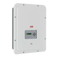
Procedure for connection to a monitoring system
Connect all the units of the RS485 chain in accordance with the “daisy-
chain” arrangement (“in-out”) observing the correspondence between
signals, and activate the termination resistance of the communication
line in the last element of the chain by switching switch a12 or a13 (to
ON position) being careful to switch the switch of the serial line used (PC
or PMU).
The communication line must also be terminated on the rst element of the chain which nor-
mally corresponds to the monitoring device.
RS485 PC/PMU
MONITORING
SYSTEM
PO
WER
AL
ARM
GFI
ESC
U
P
DOWN
EN
T
ER
PO
WER
AL
ARM
GF
I
ESC
U
P
DOWN
EN
TE
R
PO
WER
AL
AR
M
GF
I
ESC
U
P
DOWN
EN
T
ER
TRIO
TRIO
TRIO
CARD
J10
PC
OFF
TERM.
120
OFF
J8
ON
PMU
S2
S4
ON
PC
PMU
J9
PMU -T/R
J6
CARD
COM
PMU +T/R
GND COM
+5V OUT
R ON/OFF
J4
PC
SH
J7
PC +T/R
PC -T/R
GND
RTD3
RTD3
24V
-WTACH
J5
+WTACH
PT100
RTD2
RTD2
PT1000
J3
J2
PMU
CR2032
A2
COM
A2
RTD1
RTD1
A1
A1
COM
S6
NORM
S3
S7
COUNTRY/LANG SEL
K1
S8
MEMORY
ALARM
NC
C
BT1
NO
S5
PAR IND SERV
A1
J16
J14
J11
AN2 AN1
V
mA
V
mA
S1
S4
PMU
PC
S2
OFF ON
OFF ON
a13
a12
TERM.
120
S4
PMU
PC
S2
OFF ON
OFF ON
a13
a12
TERM.
120
S4
PMU
PC
S2
OFF ON
OFF ON
a13
a12
TERM.
120
OFF ON
TERM.
120
If a single inverter is connected to the monitoring system, activate the
termination resistance of the communication line by switching switch a12
or a13 (to ON position).
Set a different RS485 address on each inverter of the chain. No inverter
should have “Auto” as its address. An address can be chosen freely
from out of 2 to 63.
The address on the inverter is set through the display and the push-
button panel (see relevant chapter).
We recommend not exceeding a length of 1000m for the communication line.
No more than 62 inverters can be connected to the same RS485 line.
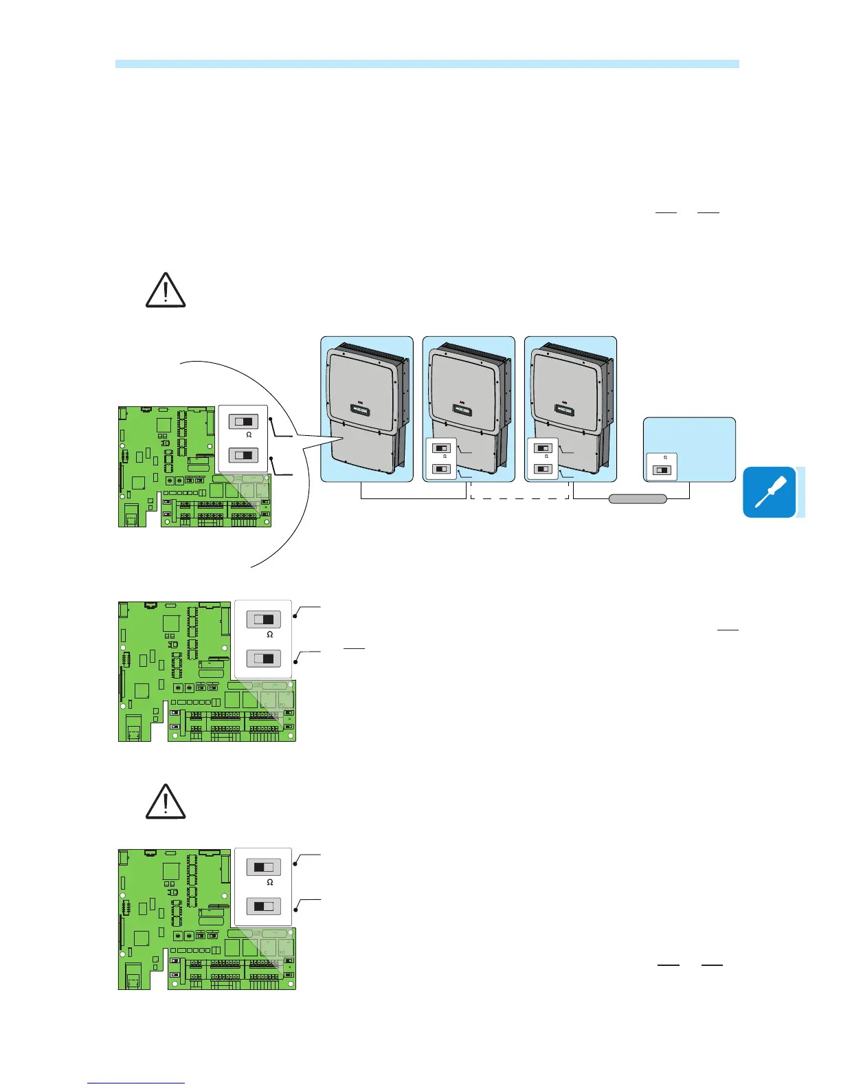
When using an RS-485 connection, if one or more inverters are added
later to the system, you must remember to return to OFF position the
switch of the termination resistance used (PC or PMU) of the inverter that
was previously the last one of the system.
Each inverter is dispatched with two (2) as the predened RS485 ad-
dress and with switch for setting termination resistance a12 or a13 to
OFF position.
CARD
J10
PC
OFF
TERM.
120
OFF
J8
ON
PMU
S2
S4
ON
PC
PMU
J9
PMU -T/R
J6
CARD
COM
PMU +T/R
GND COM
+5V OUT
R ON/OFF
J4
PC
SH
J7
PC +T/R
PC -T/R
GND
RTD3
RTD3
24V
-WTACH
J5
+WTACH
PT100
RTD2
RTD2
PT1000
J3
J2
PMU
CR2032
A2
COM
A2
RTD1
RTD1
A1
A1
COM
S6
NORM
S3
S7
COUNTRY/LANG SEL
K1
S8
MEMORY
ALARM
NC
C
BT1
NO
S5
PAR IND SERV
A1
J16
J14
J11
AN2 AN1
V
mA
V
mA
S1
S4
PMU
PC
S2
OFF ON
OFF ON

 Loading...