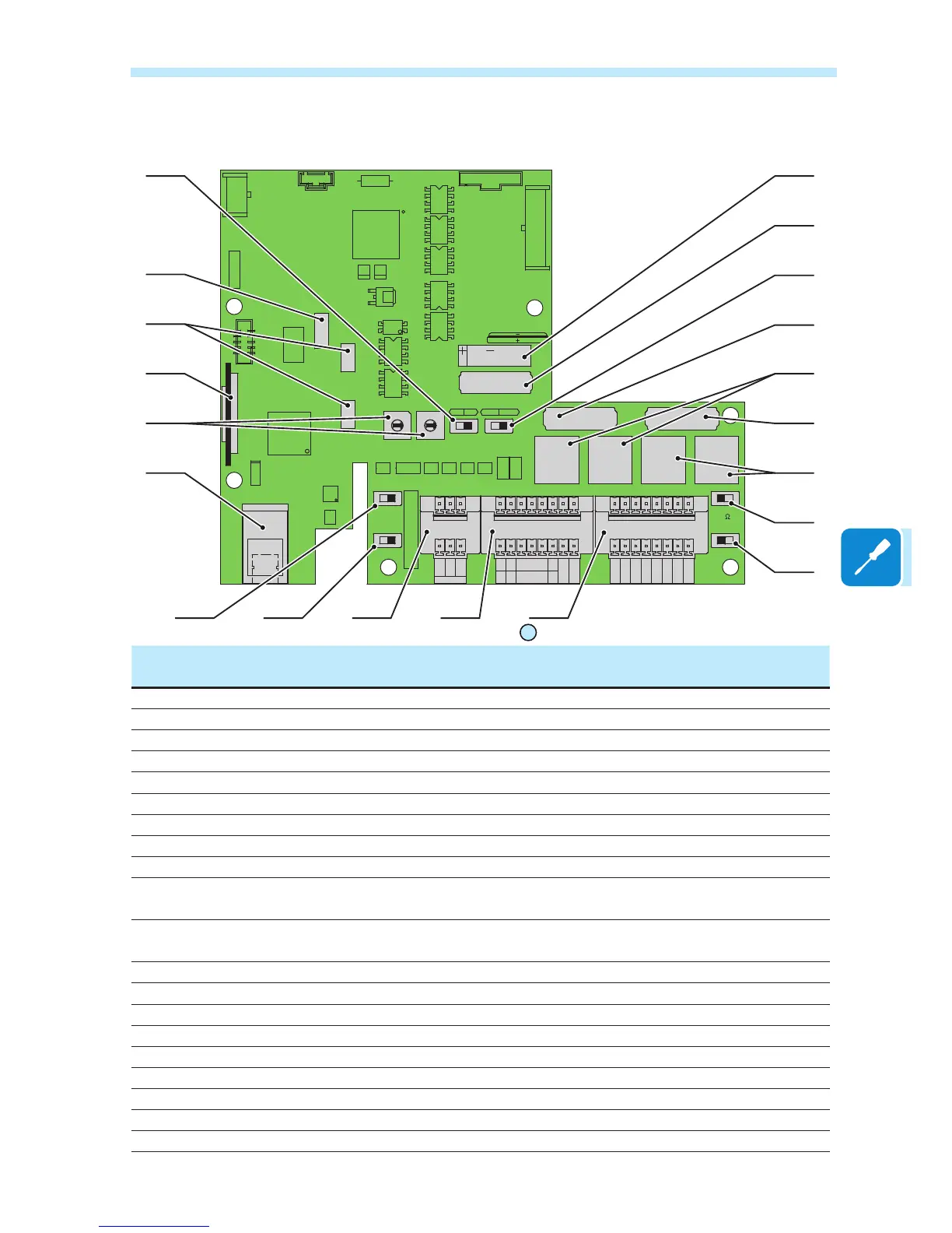
Communication card
communication card
09
Ref.
inverter
Ref.
manual
Description
S5 a01 Switch for setting parallel-connected or independent input channels
J16 a02 Connector for the installation of WIFI modules (NOT ACTIVE)
J11 e J14 a03 Connectors for radiomodule card installation
A1 a04 Housing for memory card SD CARD
S7 e S8 a05 Rotary switches for setting the standard of the country and the language of the display
J1 a06 Ethernet port (NOT ACTIVE)
S3 a07 Switch for setting analogue sensor 1 to Volts or mA
S1 a08 Switch for setting analogue sensor 2 to Volts or mA
J2 a09 Connection to the multi-function relay
J3 a10 Connectors for environmental sensors: AN1, AN2, PT100, PT1000, tachymeter (wind
version only) and power supply for environmental sensors (24 V DC)
J4 a11 Connection of the RS485 (PC) line, RS485 (PMU) line, of the auxiliary 5V and of the
remote ON/OFF
S2 a12 Switch for setting the termination resistance of the RS485 (PMU) line
S4 a13 Switch for setting the termination resistance of the RS485 (PC) line
J7 e J8 a14 Connection of the RS485 (PC) line on RJ45 connector
J10 a15 RS485 (PC) communication card housing
J5 e J6 a16 Connection of the RS485 (PMU) line on RJ45 connector
J9 a17 RS485 (PMU) communication card housing
S6 a18 Switch for setting the inverter in normal or service mode
J12 a19 Inverter data memory card housing
BT1 a20 Battery housing
CARD
J10
PC
OFF
TERM.
120
OFF
J8
ON
PMU
S2
S4
ON
PC
PMU
J9
PMU -T/R
J6
CARD
COM
PMU +T/R
GND COM
+5V OUT
R ON/OFF
J4
PC
SH
J7
PC +T/R
PC -T/R
GND
RTD3
RTD3
24V
-WTACH
J5
+WTACH
PT100
RTD2
RTD2
PT1000
J3
J2
PMU
CR2032
A2
COM
A2
RTD1
RTD1
A1
A1
COM
S6
NORM
S3
S7
COUNTRY/LANG SEL
K1
S8
MEMORY
ALARM
NC
C
BT1
NO
S5
PAR IND SERV
A1
J16
J14
J11
AN2 AN1
V
mA
V
mA
S1

 Loading...