Structure and function
2-8 3HDA000057A8519-001 Torch cleaner TC 2013
Assembly instructions
Height adjustment without TCP gauging*
Height adjustment with TCP gauging*
2.3.2.2 Clamping cylinder with V-block (Pos. 2a....2c)
The welding torch is pressed against the clamping V-block (2b) by pneumatic clamping cylinder
(2a) and is thus firmly clamped in during milling. As the welding torch is clamped centrally with
respect to the milling cutter, the V-block must be set to the appropriate torch diameter with a suit-
able spacer plate (2c) (for selection of spacer plates see Table 2-1).
2.3.2.3 Motor pack (Pos. 3)
The air motor is integrated into the pneumatic feed cylinder and thus forms a common motor pack.
The shaft end of the air motor carries the milling cutter.
2.3.2.4 Milling cutter (Pos. 4)
There are suitable milling cutters for the welding cutter nozzles concerned for internal and external
cleaning.
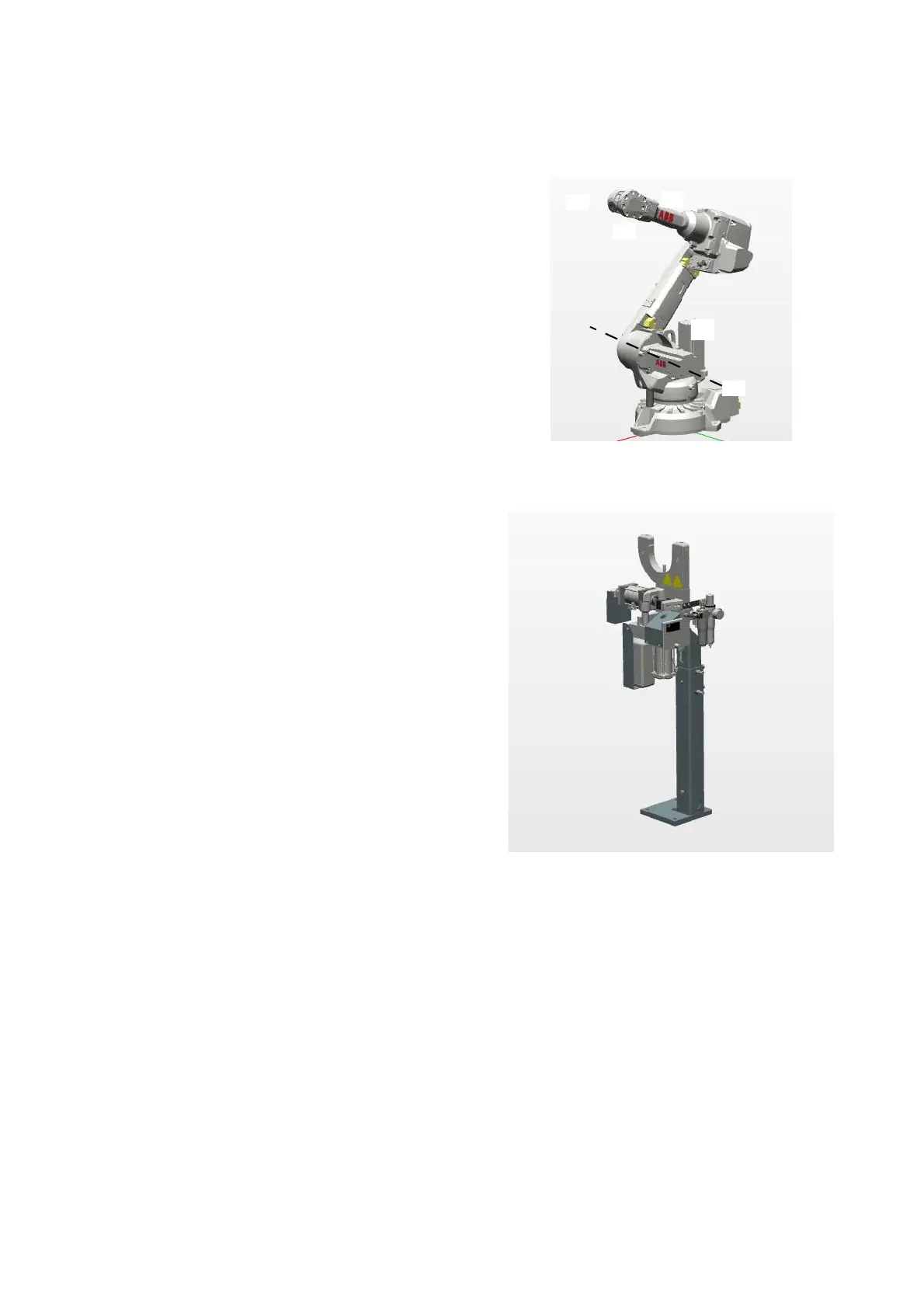
It is recommended that the optimum height is
determined depending on the center of the ful-
crum of robot axis 2 (guide value).
Optimum height means that the robot arm
reaches the TC2013 by the shortest route and
can swivel in horizontally with minimal height
movement.
The height should, as a rule, be set approx. 200
mm lower than in the case of the TC 2013 with-
out TCP gauging.