Structure and function
Torch cleaner TC 2013 3HDA000057A8519-001 2-9
Assembly instructions
2.3.2.5 Spray device (Pos. 5)
The spray device consists of a 3/2-way valve, the spray head and a release agent tank with liquid
sensor. The spray device wets the cleaned gas nozzle with release agent free of silicone and sol-
vent. This prevents the early deposition of weld spatter.
2.3.2.6 Ventilation circuit with valves and maintenance unit (Pos. 6)
For explanations on the ventilation circuit, see Section 2.9 "Pneumatic plan".
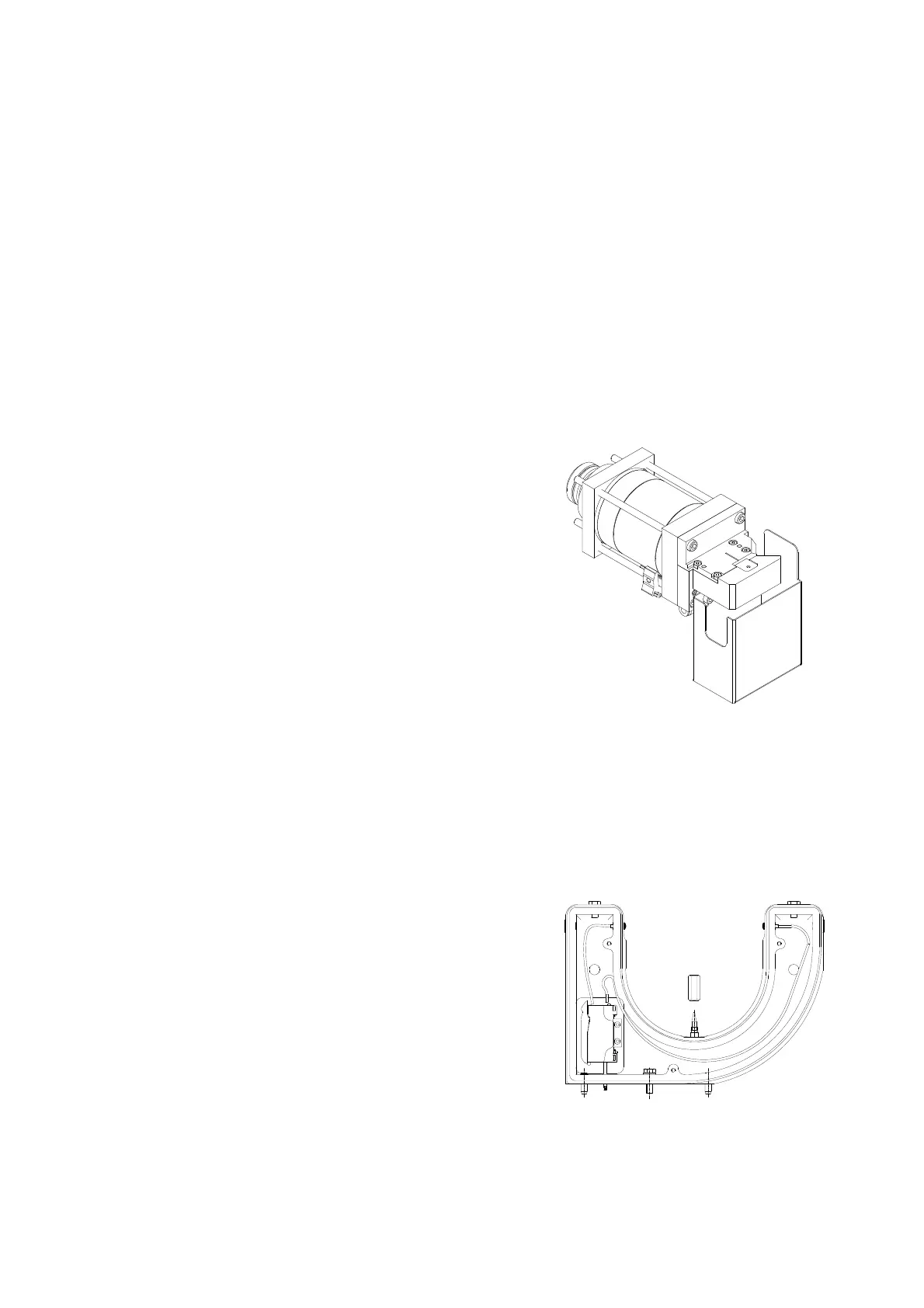
2.3.2.7 Wire cutter (Pos. 7*) - Option
The wire cutter is an add-on module for the TC 2013 and can be retrofitted at any time.
The cutting plate is mechanically connected to the clamping cylinder of the TC 2013 and does not
require any additional control elements.
Subsequent addition to TC 2013
Instructions for retrofitting of the wire cutter can be found in Chapter 3.6 Assembly of the wire cut-
ter on the TC 2013.
2.3.2.8 TCP gauging (Pos. 8*) - Option
TCP gauging is an add-on module for the TC 2013 and can be retrofitted at any time.
Subsequent addition to TC 2013
Instructions for retrofitting of TCP gauging can be found in Chapter 4.7 Assembly.
With the wire cutter the
– welding wire is cut to the desired length,
– bent or excessively projecting wire is cut off,
– the end of the wire is cut off before each torch clean-
ing and where appropriate before each TCP gaug-
ing,
– and slag formed at the end of the wire is cut off.
As a result arc ignition behaviour is improved and avail-
ability is increased.
TCP gauging is used solely to gauge and adjust the
robot tool center point (TCP).
Deviations of the torch TCP are gauged. If the toler-
ance is exceeded, the torch system of coordinates is
automatically corrected.