Do you have a question about the ABB VUCG.N and is the answer not in the manual?
The document describes the ABB VUC series of on-load tap-changers (OLTCs), which are designed for use in power transformers. These tap-changers are built on the same platform as conventional UC tap-changers, sharing well-proven selectors, diverter switch housings, and drive trains.
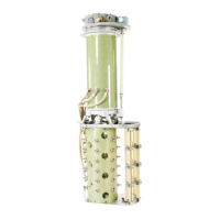
The VUC tap-changers are designed to regulate voltage in power transformers by changing the tapping point of the transformer windings while the transformer is energized. This is achieved through a two-section design: a diverter switch and a tap selector. The diverter switch, with its own separate housing, uses vacuum interrupters for arc quenching. The tap selector, mounted beneath the diverter switch housing, typically includes a fine tap selector and a change-over selector. Power for operation is supplied by an external motor-drive mechanism, transmitted via shafts and bevel gears.
The VUC diverter switches, utilizing vacuum interrupters, minimize contamination of the insulating liquid from current commutation sparks and heat dissipation. This separation ensures that the insulating liquid of the tap-changer does not affect the oil analysis of the main transformer tank.
The switching sequence for VUCG (Vacuum Under Current, G-type) involves an asymmetrical pennant cycle, always starting with the main contact. The load current is commutated from one tap to another with the aid of vacuum interrupters and auxiliary contacts. The sequence involves opening the main vacuum interrupter, routing current through a transition resistor, rotating the main contact to connect to the new tap, closing the main vacuum interrupter, and finally disconnecting the transition resistor by opening the resistor vacuum interrupter.
For VUCL (Vacuum Under Current, L-type), the switching sequence also follows an asymmetrical pennant cycle. During normal operation, the current flows through a bypass contact. When commuting the load, the bypass contact is opened first, then the main vacuum interrupter, allowing current to flow through the transition resistor. The main contact is then rotated to the new tap, the main vacuum interrupter closes, the bypass contact is reconnected, and finally, the transition resistor is disconnected by opening the resistor vacuum interrupter.
The VUC series offers different types of regulation:
Connections can be configured for:
Type Designation: VUCG/VUCL XXXX/YYYY/Z, where XXXX/YYYY/Z denotes impulse withstand voltage to earth, rated through-current, and tap selector size.
Impulse Withstand Voltage to Earth:
Maximum Rated Through-Current: Determined by the lowest rating of the diverter switch and tap selector.
Rated Phase Step Voltage: A function of the rated through-current, with diagrams provided for VUCG and VUCL. For VUCG, step voltage ranges from 250V to 3500V depending on current. For VUCL, it ranges up to 4500V.
Maximum Number of Positions:
Short-Circuit Current Strength: Verified with three applications of 3 seconds duration (at least 2.5 times rms value) without contact movement.
Insulation Levels (to earth):
Highest Phase Service Voltage Across Regulating Winding: Varies by connection type and shielding, e.g., VUCG.N,B with C tap selector: 35 kV (without shielding), 40 kV (with shielding).
Oil Temperature: Normal operating range is -25 to +105 °C. Operation possible under certain conditions down to -40 °C with low viscosity oil. No operations allowed below -40 °C or above +115 °C.
Insulating Liquids: All data based on mineral oil (IEC 60296, 2012-02). Other liquids like esters and HMWH are accepted under certain conditions; consult ABB for advice.
Mounting: VUC tap-changers can be delivered for cover-mounting or yoke-mounting onto the transformer. Diverter Switch Housing: High-quality seals ensure vacuum and overpressure-proof performance. The top section forms the flange for mounting to the transformer cover and carries the gear box for operating shafts. It includes connections for the conservator pipe, draining, sampling, earthing terminal, supervisory device, and cover with gasket. Tap Selectors: Available in sizes C, III, and F. All types use a glass fiber reinforced epoxy cylinder for the fine selector. Change-over selector contacts are made of silver for long-term stability. Motor-Drive Mechanism: Provides the drive for tap-changer operation through a series of gears and a drive shaft. Designed for long service intervals and reliability. Enforced Current Splitting: Can be used when the diverter switch has a lower current rating than the tap selector, or when multiple tap-changers operate in parallel in the same phase. Requires careful impedance matching. Tie-in Resistor and Switch: Used when capacitive controlled voltage across the change-over selector is too high. Tie-in resistors are connected between the middle of the tapped winding and the connection point on the bottom of the diverter switch housing. A tie-in resistor switch (available for tap selectors III and F) can connect resistors only when needed to limit no-load losses.
Reliability and Long Life: Diverter switches are designed for high reliability and long life with minimum maintenance and easy inspection. Vacuum Interrupters: Have a very long lifetime and are mounted for easy replacement, especially for industrial applications with high operation counts. Contact Life: Always 600,000 operations for VUC type tap-changers, regardless of rated through-current. Stated on the rating plate. Motor-Drive Mechanism: Should be visually inspected annually. Pressure Monitoring: During service, a maximum of 70 kPa pressure difference between the tap-changer diverter switch housing and the atmosphere is allowed. Oil Conservator: Separate oil conservators for the transformer and tap-changer are recommended. The oil volume should ensure the oil level remains within the indicator range at all predictable temperatures. Oil sampling valves should be accessible from ground level. Protection Devices: Can be equipped with a pressure relay (standard) and an oil flow relay. A pressure relief device with an alarm signal is also available. Drying Process: The diverter switch can participate in the drying process, but must not be maneuvered until submersed in oil. Maintenance Intervals: One maintenance (cleaning and inspection) is recommended during the transformer life, with 15 years as a guideline.
| Brand | ABB |
|---|---|
| Model | VUCG.N |
| Category | Industrial Equipment |
| Language | English |